Cirkit Designer Logo
Cirkit Designer
Your all-in-one circuit design IDE
Home / 
Component Documentation

How to Use esp32: Examples, Pinouts, and Specs

Image of esp32
Cirkit Designer LogoDesign with esp32 in Cirkit Designer

Introduction

The ESP32 is a low-cost, low-power system on a chip (SoC) developed by Espressif Systems. It features integrated Wi-Fi and Bluetooth capabilities, making it an ideal choice for Internet of Things (IoT) applications, smart devices, and embedded systems. The ESP32 is highly versatile, offering dual-core processing, a wide range of GPIO pins, and support for various communication protocols.

Explore Projects Built with esp32

Use Cirkit Designer to design, explore, and prototype these projects online. Some projects support real-time simulation. Click "Open Project" to start designing instantly!
ESP32-Controlled OLED Display and Servo with DotStar LED Strip and Audio Output
Image of Arena 2: A project utilizing esp32 in a practical application
This circuit features an ESP32 microcontroller driving a variety of components. It controls an OLED display for visual output, a DotStar LED strip for lighting effects, a PAM8403 audio amplifier connected to a speaker for sound output, and a PCA9685 PWM Servo Breakout to manage a servo motor. The ESP32 also interfaces with a piezo speaker for additional sound generation, and the circuit is powered by a 18650 Li-ion battery setup with a TP4056 charging module. The ESP32's embedded code handles the display animation on the OLED.
Cirkit Designer LogoOpen Project in Cirkit Designer
ESP32-Based Sensor Monitoring System with OLED Display and E-Stop
Image of MVP_design: A project utilizing esp32 in a practical application
This circuit features an ESP32 microcontroller that interfaces with a variety of sensors and output devices. It is powered by a Lipo battery through a buck converter, ensuring a stable voltage supply. The ESP32 collects data from a DHT11 temperature and humidity sensor and a vibration sensor, controls a buzzer, and displays information on an OLED screen. An emergency stop (E Stop) is connected for safety purposes, allowing the system to be quickly deactivated.
Cirkit Designer LogoOpen Project in Cirkit Designer
ESP32-Based Environmental Monitoring System with Motion Detection
Image of pro: A project utilizing esp32 in a practical application
This circuit features an ESP32 microcontroller on a baseboard that interfaces with a PIR sensor for motion detection, a DHT22 sensor for measuring temperature and humidity, and a BH1750 sensor for detecting ambient light levels. The ESP32 is configured to communicate with the BH1750 using I2C protocol, with GPIO22 and GPIO21 serving as the SCL and SDA lines, respectively. Power is supplied to the sensors from the ESP32's voltage output pins, and sensor outputs are connected to designated GPIO pins for data acquisition.
Cirkit Designer LogoOpen Project in Cirkit Designer
ESP32-Based Smart Weather Station with Wi-Fi Connectivity
Image of flowchart 3D: A project utilizing esp32 in a practical application
This circuit features an ESP32 microcontroller interfacing with various sensors and modules, including a DHT22 temperature and humidity sensor, an ESP32 CAM for image capture, an I2C LCD screen for display, a load cell with an HX711 interface for weight measurement, and a buzzer for audio alerts. The ESP32 handles data acquisition, processing, and communication with these peripherals to create a multi-functional monitoring and alert system.
Cirkit Designer LogoOpen Project in Cirkit Designer

Explore Projects Built with esp32

Use Cirkit Designer to design, explore, and prototype these projects online. Some projects support real-time simulation. Click "Open Project" to start designing instantly!
Image of Arena 2: A project utilizing esp32 in a practical application
ESP32-Controlled OLED Display and Servo with DotStar LED Strip and Audio Output
This circuit features an ESP32 microcontroller driving a variety of components. It controls an OLED display for visual output, a DotStar LED strip for lighting effects, a PAM8403 audio amplifier connected to a speaker for sound output, and a PCA9685 PWM Servo Breakout to manage a servo motor. The ESP32 also interfaces with a piezo speaker for additional sound generation, and the circuit is powered by a 18650 Li-ion battery setup with a TP4056 charging module. The ESP32's embedded code handles the display animation on the OLED.
Cirkit Designer LogoOpen Project in Cirkit Designer
Image of MVP_design: A project utilizing esp32 in a practical application
ESP32-Based Sensor Monitoring System with OLED Display and E-Stop
This circuit features an ESP32 microcontroller that interfaces with a variety of sensors and output devices. It is powered by a Lipo battery through a buck converter, ensuring a stable voltage supply. The ESP32 collects data from a DHT11 temperature and humidity sensor and a vibration sensor, controls a buzzer, and displays information on an OLED screen. An emergency stop (E Stop) is connected for safety purposes, allowing the system to be quickly deactivated.
Cirkit Designer LogoOpen Project in Cirkit Designer
Image of pro: A project utilizing esp32 in a practical application
ESP32-Based Environmental Monitoring System with Motion Detection
This circuit features an ESP32 microcontroller on a baseboard that interfaces with a PIR sensor for motion detection, a DHT22 sensor for measuring temperature and humidity, and a BH1750 sensor for detecting ambient light levels. The ESP32 is configured to communicate with the BH1750 using I2C protocol, with GPIO22 and GPIO21 serving as the SCL and SDA lines, respectively. Power is supplied to the sensors from the ESP32's voltage output pins, and sensor outputs are connected to designated GPIO pins for data acquisition.
Cirkit Designer LogoOpen Project in Cirkit Designer
Image of flowchart 3D: A project utilizing esp32 in a practical application
ESP32-Based Smart Weather Station with Wi-Fi Connectivity
This circuit features an ESP32 microcontroller interfacing with various sensors and modules, including a DHT22 temperature and humidity sensor, an ESP32 CAM for image capture, an I2C LCD screen for display, a load cell with an HX711 interface for weight measurement, and a buzzer for audio alerts. The ESP32 handles data acquisition, processing, and communication with these peripherals to create a multi-functional monitoring and alert system.
Cirkit Designer LogoOpen Project in Cirkit Designer

Common Applications and Use Cases

  • IoT devices (e.g., smart home automation, sensors, and actuators)
  • Wearable technology
  • Wireless communication hubs
  • Robotics and drones
  • Data logging and monitoring systems
  • Prototyping and educational projects

Technical Specifications

The ESP32 is packed with features that make it a powerful and flexible component for a wide range of applications. Below are its key technical specifications:

Key Technical Details

  • Processor: Dual-core Xtensa® 32-bit LX6 microprocessor
  • Clock Speed: Up to 240 MHz
  • RAM: 520 KB SRAM
  • Flash Memory: Typically 4 MB (varies by module)
  • Wi-Fi: 802.11 b/g/n (2.4 GHz)
  • Bluetooth: v4.2 BR/EDR and BLE
  • Operating Voltage: 3.3V
  • GPIO Pins: 34 (multipurpose, including ADC, DAC, PWM, I2C, SPI, UART)
  • ADC Channels: 18 (12-bit resolution)
  • DAC Channels: 2 (8-bit resolution)
  • Power Consumption: Ultra-low power modes available (as low as 5 µA in deep sleep)

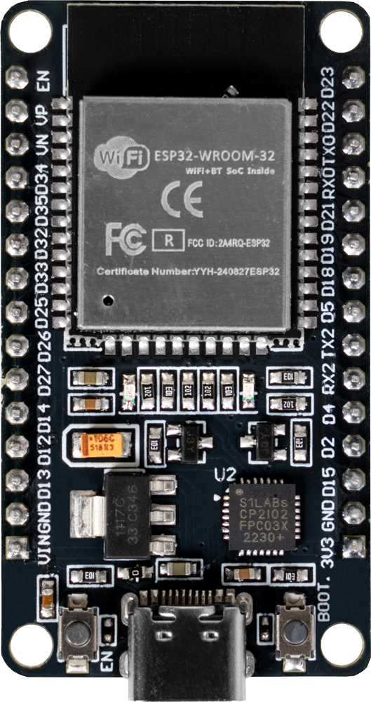
Pin Configuration and Descriptions

The ESP32 has a variety of pins for different functionalities. Below is a table summarizing the key pins and their descriptions:

Pin Name Type Description
GPIO0 Input/Output General-purpose I/O, used for boot mode selection during startup.
GPIO2 Input/Output General-purpose I/O, often used as a bootstrapping pin.
GPIO12 Input/Output General-purpose I/O, can be used for ADC or other functions.
GPIO13 Input/Output General-purpose I/O, supports PWM and other functions.
GPIO15 Input/Output General-purpose I/O, supports ADC, PWM, and other functions.
EN Input Chip enable pin. Pull high to enable the chip, pull low to disable.
3V3 Power 3.3V power supply input/output.
GND Power Ground connection.
TX0 (GPIO1) Output UART0 transmit pin, used for serial communication.
RX0 (GPIO3) Input UART0 receive pin, used for serial communication.

Note: The ESP32 has many more GPIO pins and functionalities. Refer to the official datasheet for a complete pinout.

Usage Instructions

The ESP32 can be used in a variety of circuits and projects. Below are the steps and best practices for using the ESP32 effectively:

How to Use the ESP32 in a Circuit

  1. Powering the ESP32:

    • Provide a stable 3.3V power supply to the 3V3 pin.
    • Ensure the ground (GND) is connected to the circuit's ground.
  2. Programming the ESP32:

    • Use a USB-to-serial adapter or a development board with a built-in USB interface.
    • Install the ESP32 board package in the Arduino IDE or use the ESP-IDF framework for advanced development.
  3. Connecting Peripherals:

    • Use GPIO pins for connecting sensors, actuators, or other peripherals.
    • Configure the pins in your code according to the desired functionality (e.g., input, output, ADC).
  4. Uploading Code:

    • Connect the ESP32 to your computer via USB.
    • Select the correct board and port in the Arduino IDE.
    • Write or load your code and click "Upload."

Important Considerations and Best Practices

  • Voltage Levels: The ESP32 operates at 3.3V. Avoid applying 5V to GPIO pins to prevent damage.
  • Boot Mode: Ensure GPIO0 is pulled low during boot to enter programming mode.
  • Power Supply: Use a decoupling capacitor (e.g., 10 µF) near the power pins to stabilize the voltage.
  • Wi-Fi Interference: Place the ESP32 away from metal objects or other sources of interference for optimal Wi-Fi performance.

Example Code for Arduino UNO Integration

Below is an example of how to use the ESP32 to blink an LED connected to GPIO2:

// Define the GPIO pin for the LED
#define LED_PIN 2

void setup() {
  // Initialize the LED pin as an output
  pinMode(LED_PIN, OUTPUT);
}

void loop() {
  // Turn the LED on
  digitalWrite(LED_PIN, HIGH);
  delay(1000); // Wait for 1 second

  // Turn the LED off
  digitalWrite(LED_PIN, LOW);
  delay(1000); // Wait for 1 second
}

Tip: Ensure the ESP32 is properly connected to your computer and the correct board is selected in the Arduino IDE before uploading the code.

Troubleshooting and FAQs

Common Issues and Solutions

  1. ESP32 Not Detected by Computer:

    • Ensure the USB cable is functional and supports data transfer.
    • Install the correct USB-to-serial driver for your operating system.
  2. Code Upload Fails:

    • Check that GPIO0 is pulled low during boot.
    • Verify the correct COM port and board are selected in the Arduino IDE.
  3. Wi-Fi Connection Issues:

    • Double-check the SSID and password in your code.
    • Ensure the ESP32 is within range of the Wi-Fi router.
  4. Random Resets or Instability:

    • Verify the power supply is stable and capable of providing sufficient current.
    • Add decoupling capacitors near the power pins.

FAQs

Q: Can the ESP32 operate on 5V?
A: No, the ESP32 operates at 3.3V. Applying 5V to GPIO pins can damage the chip.

Q: How do I enter deep sleep mode?
A: Use the esp_deep_sleep_start() function in your code. Refer to the ESP-IDF documentation for detailed instructions.

Q: Can I use the ESP32 with Bluetooth and Wi-Fi simultaneously?
A: Yes, the ESP32 supports simultaneous use of Bluetooth and Wi-Fi, but performance may vary depending on the application.

Q: What is the maximum range of the ESP32's Wi-Fi?
A: The range depends on environmental factors but is typically around 50 meters indoors and 200 meters outdoors.

By following this documentation, you can effectively use the ESP32 in your projects and troubleshoot common issues with ease.