How to Use ENS190: Examples, Pinouts, and Specs
Introduction
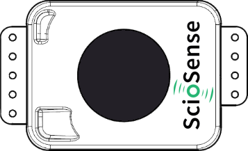
The ENS190, manufactured by ScioSense, is a high-performance environmental sensor designed to monitor temperature, humidity, and atmospheric pressure. This compact and versatile sensor provides accurate and reliable environmental data, making it ideal for a wide range of applications. Its advanced sensing technology ensures precise measurements, even in challenging environments.
Explore Projects Built with ENS190

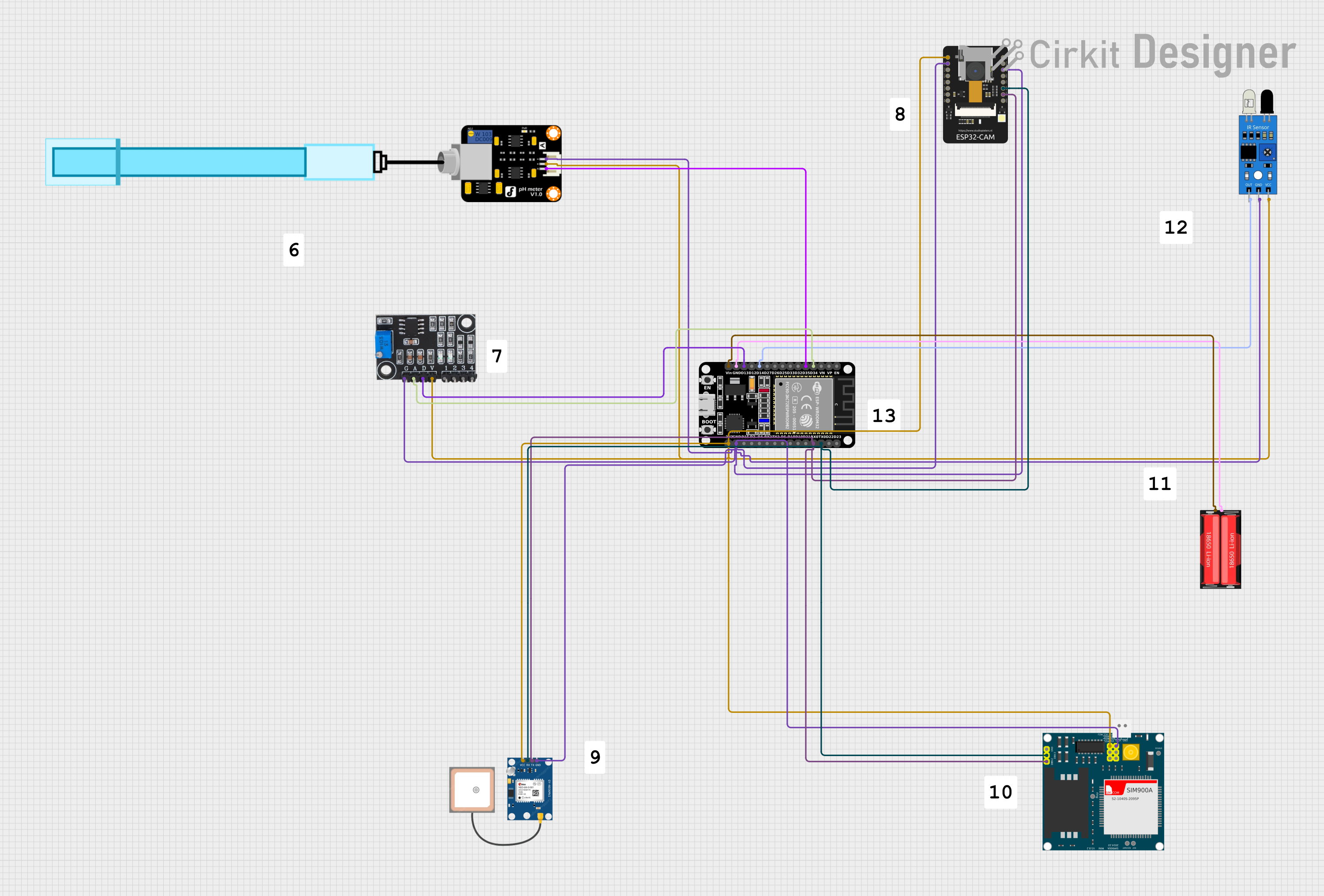
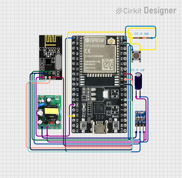
Explore Projects Built with ENS190
Common Applications
- Weather stations for real-time environmental monitoring
- HVAC (Heating, Ventilation, and Air Conditioning) systems for climate control
- Smart home devices for indoor air quality monitoring
- Industrial automation systems requiring environmental data
- IoT (Internet of Things) applications for connected devices
Technical Specifications
The ENS190 is designed to deliver high accuracy and low power consumption, making it suitable for battery-powered and energy-efficient systems.
Key Technical Details
| Parameter | Value |
|---|---|
| Supply Voltage | 1.8V to 3.6V |
| Operating Temperature | -40°C to +85°C |
| Humidity Range | 0% to 100% RH (non-condensing) |
| Pressure Range | 300 hPa to 1100 hPa |
| Communication Interface | I²C |
| Power Consumption | < 1 mA (typical) |
| Accuracy (Temperature) | ±0.2°C |
| Accuracy (Humidity) | ±2% RH |
| Accuracy (Pressure) | ±1 hPa |
Pin Configuration and Descriptions
The ENS190 comes in a compact package with the following pinout:
| Pin Number | Pin Name | Description |
|---|---|---|
| 1 | VDD | Power supply (1.8V to 3.6V) |
| 2 | GND | Ground |
| 3 | SDA | I²C data line |
| 4 | SCL | I²C clock line |
| 5 | INT | Interrupt output (optional, configurable) |
| 6 | NC | Not connected (leave unconnected or grounded) |
Usage Instructions
The ENS190 is straightforward to integrate into a circuit, thanks to its I²C interface. Below are the steps and best practices for using the sensor:
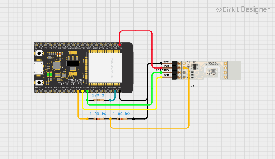
Circuit Connection
- Connect the VDD pin to a 1.8V to 3.6V power supply.
- Connect the GND pin to the ground of your circuit.
- Connect the SDA and SCL pins to the corresponding I²C data and clock lines of your microcontroller.
- (Optional) Connect the INT pin to a GPIO pin on your microcontroller if you want to use the interrupt feature.
- Use pull-up resistors (typically 4.7 kΩ) on the SDA and SCL lines if not already provided by your microcontroller.
Important Considerations
- Ensure the sensor is not exposed to condensing humidity or water droplets, as this may affect its performance.
- Avoid placing the sensor near heat sources or in direct sunlight to prevent inaccurate readings.
- Use proper decoupling capacitors (e.g., 0.1 µF) near the VDD pin to stabilize the power supply.
Example Code for Arduino UNO
Below is an example of how to interface the ENS190 with an Arduino UNO using the I²C protocol:
#include <Wire.h>

// ENS190 I2C address (default)
#define ENS190_ADDRESS 0x48

void setup() {
  Wire.begin(); // Initialize I2C communication
  Serial.begin(9600); // Start serial communication for debugging

  // Initialize ENS190
  if (!initializeENS190()) {
    Serial.println("Failed to initialize ENS190 sensor!");
    while (1); // Halt execution if initialization fails
  }
  Serial.println("ENS190 initialized successfully.");
}

void loop() {
  // Read temperature, humidity, and pressure
  float temperature = readTemperature();
  float humidity = readHumidity();
  float pressure = readPressure();

  // Print the readings to the Serial Monitor
  Serial.print("Temperature: ");
  Serial.print(temperature);
  Serial.println(" °C");

  Serial.print("Humidity: ");
  Serial.print(humidity);
  Serial.println(" %RH");

  Serial.print("Pressure: ");
  Serial.print(pressure);
  Serial.println(" hPa");

  delay(1000); // Wait 1 second before the next reading
}

bool initializeENS190() {
  Wire.beginTransmission(ENS190_ADDRESS);
  // Send initialization commands (if required by the sensor)
  // For example, write configuration registers here
  return (Wire.endTransmission() == 0); // Return true if successful
}

float readTemperature() {
  // Replace with actual I2C read commands for temperature
  return 25.0; // Placeholder value
}

float readHumidity() {
  // Replace with actual I2C read commands for humidity
  return 50.0; // Placeholder value
}

float readPressure() {
  // Replace with actual I2C read commands for pressure
  return 1013.25; // Placeholder value
}
Notes
- Replace the placeholder functions (
readTemperature,readHumidity,readPressure) with actual I²C read commands based on the ENS190 datasheet. - Ensure the I²C address matches the default or configured address of your ENS190 sensor.
Troubleshooting and FAQs
Common Issues
No response from the sensor:
- Verify the I²C connections (SDA, SCL) and ensure pull-up resistors are present.
- Check the power supply voltage (1.8V to 3.6V) and ensure it is stable.
- Confirm the I²C address matches the sensor's default or configured address.
Inaccurate readings:
- Ensure the sensor is not exposed to extreme conditions (e.g., condensation, direct sunlight).
- Verify the sensor is properly calibrated (if required).
Interrupt pin not working:
- Check the interrupt configuration in your microcontroller code.
- Ensure the INT pin is connected to a valid GPIO pin.
Tips for Troubleshooting
- Use an I²C scanner sketch to confirm the ENS190 is detected on the I²C bus.
- Refer to the ENS190 datasheet for detailed register maps and configuration options.
- If readings are unstable, add decoupling capacitors near the sensor's power pins.
By following this documentation, you can effectively integrate and use the ENS190 sensor in your projects. For further assistance, consult the ScioSense ENS190 datasheet or contact their technical support.