How to Use heart beat sensor: Examples, Pinouts, and Specs

Introduction
A heart beat sensor is a device that detects and measures the heart rate of an individual, typically using optical or electrical methods to monitor blood flow and provide real-time data. These sensors are widely used in medical devices, fitness trackers, and health monitoring systems. By providing accurate and non-invasive heart rate measurements, they are essential for applications such as fitness tracking, stress monitoring, and patient care.
Explore Projects Built with heart beat sensor

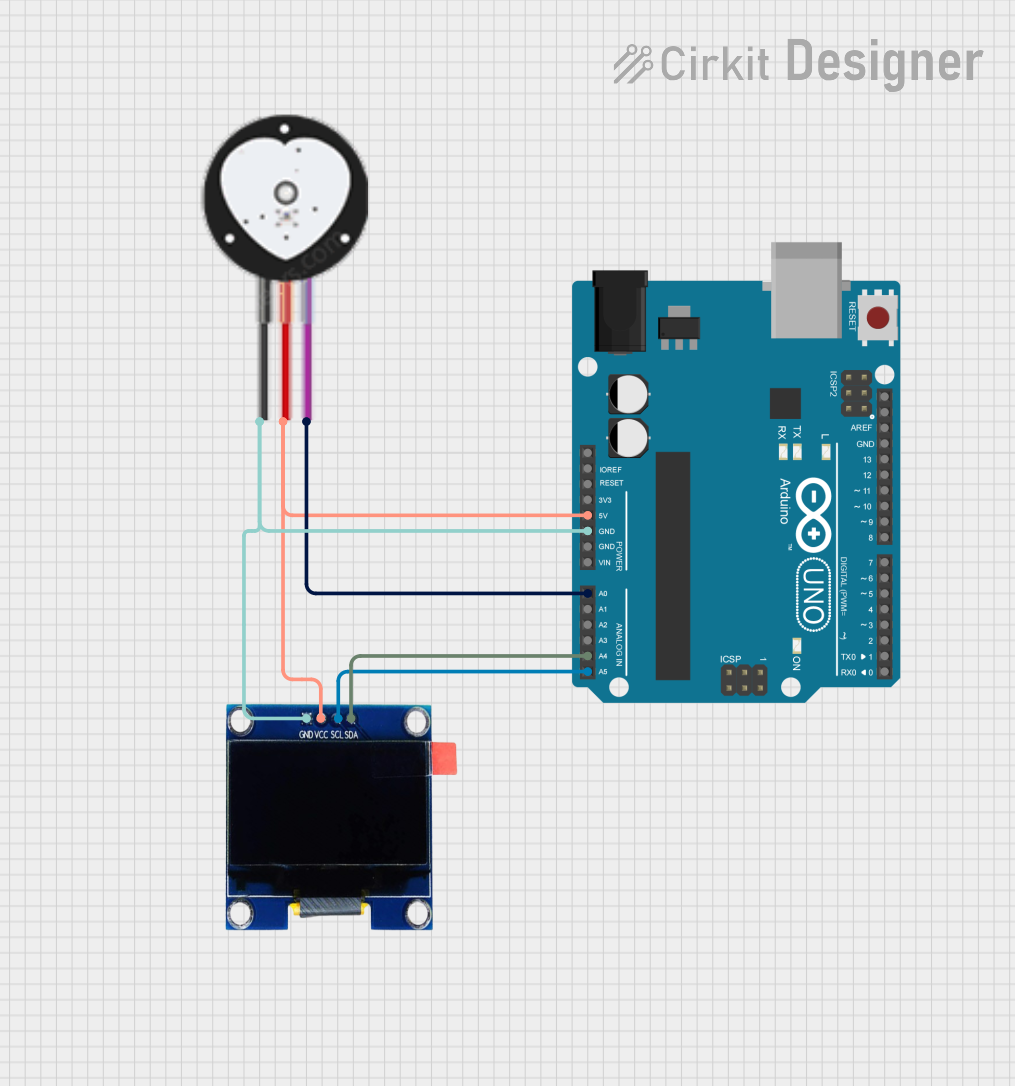
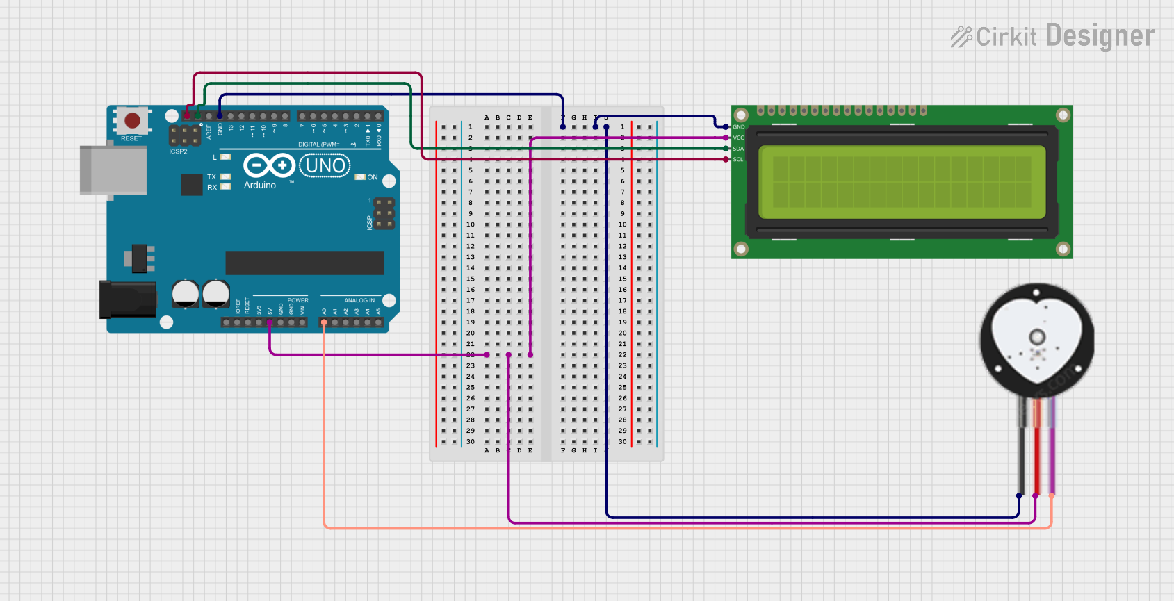
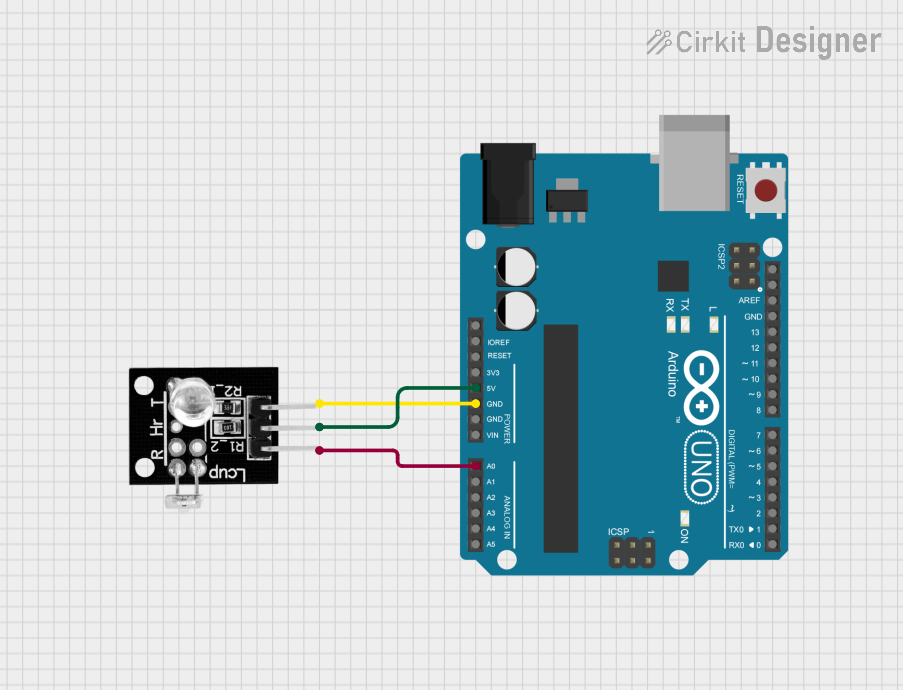
Explore Projects Built with heart beat sensor
Common Applications and Use Cases
- Fitness trackers and smartwatches
- Medical monitoring devices (e.g., ECG machines)
- Stress and emotion monitoring systems
- DIY health monitoring projects
- Sports performance analysis
Technical Specifications
Below are the general technical specifications for a typical optical heart beat sensor module (e.g., the KY-039 or similar):
| Parameter | Value |
|---|---|
| Operating Voltage | 3.3V to 5V |
| Operating Current | 4mA to 6mA |
| Output Signal | Analog voltage signal |
| Detection Method | Optical (infrared light reflection) |
| Sensor Type | Phototransistor and IR LED |
| Dimensions | ~20mm x 10mm x 5mm |
| Operating Temperature | -20°C to 70°C |
Pin Configuration and Descriptions
| Pin Name | Description |
|---|---|
| VCC | Power supply input (3.3V to 5V) |
| GND | Ground connection |
| OUT | Analog output signal (heart rate data) |
Usage Instructions
How to Use the Component in a Circuit
- Power the Sensor: Connect the
VCCpin to a 3.3V or 5V power source and theGNDpin to the ground of your circuit. - Connect the Output: Connect the
OUTpin to an analog input pin of your microcontroller (e.g., Arduino). - Place the Sensor: Position the sensor so that the IR LED and phototransistor are in contact with or close to the skin (e.g., fingertip or earlobe).
- Read the Signal: The sensor outputs an analog voltage signal that corresponds to the heart rate. Use an analog-to-digital converter (ADC) to process the signal.
Important Considerations and Best Practices
- Placement: Ensure the sensor is securely placed on the skin for accurate readings. Avoid excessive movement, as it can introduce noise.
- Ambient Light: Minimize exposure to ambient light, as it can interfere with the IR signal. Consider using a dark enclosure for the sensor.
- Signal Filtering: Use a low-pass filter or software-based signal processing to remove noise and extract the heart rate signal.
- Power Supply: Use a stable power source to avoid fluctuations in the sensor's output.
Example: Connecting to an Arduino UNO
Below is an example of how to use the heart beat sensor with an Arduino UNO to read and display heart rate data:
// Heart Beat Sensor Example with Arduino UNO
// Connect the sensor's VCC to 5V, GND to GND, and OUT to A0 (analog pin).

const int sensorPin = A0; // Analog pin connected to the sensor's OUT pin
int sensorValue = 0;      // Variable to store the sensor reading

void setup() {
  Serial.begin(9600); // Initialize serial communication at 9600 baud
  pinMode(sensorPin, INPUT); // Set the sensor pin as input
}

void loop() {
  sensorValue = analogRead(sensorPin); // Read the analog value from the sensor
  Serial.print("Heart Beat Sensor Value: ");
  Serial.println(sensorValue); // Print the sensor value to the Serial Monitor

  delay(10); // Small delay to stabilize readings
}
Notes:
- Use the Serial Monitor in the Arduino IDE to view the sensor readings.
- For accurate heart rate calculation, additional signal processing (e.g., peak detection) is required.
Troubleshooting and FAQs
Common Issues and Solutions
No Output Signal:
- Cause: Incorrect wiring or loose connections.
- Solution: Double-check the connections to ensure the
VCC,GND, andOUTpins are properly connected.
Inconsistent Readings:
- Cause: Excessive movement or poor sensor placement.
- Solution: Ensure the sensor is securely placed on the skin and minimize movement during measurement.
High Noise in Output:
- Cause: Ambient light interference or unstable power supply.
- Solution: Shield the sensor from ambient light and use a stable power source.
Low Sensitivity:
- Cause: Dirty or damaged sensor surface.
- Solution: Clean the sensor surface with a soft, dry cloth and ensure it is not damaged.
FAQs
Q1: Can this sensor measure heart rate directly?
A1: No, the sensor provides an analog signal corresponding to blood flow. Additional signal processing is required to calculate the heart rate.
Q2: Can I use this sensor with a 3.3V microcontroller?
A2: Yes, the sensor operates within a voltage range of 3.3V to 5V.
Q3: How do I calculate the heart rate from the sensor output?
A3: Use a peak detection algorithm to count the number of peaks in the signal over a fixed time period (e.g., 1 minute) and calculate beats per minute (BPM).
Q4: Is this sensor suitable for medical-grade applications?
A4: No, this sensor is intended for hobbyist and educational purposes. For medical-grade applications, use certified devices.