Cirkit Designer Logo
Cirkit Designer
Your all-in-one circuit design IDE
Home / 
Component Documentation

How to Use Dioda schottky: Examples, Pinouts, and Specs

Image of Dioda schottky
Cirkit Designer LogoDesign with Dioda schottky in Cirkit Designer

Introduction

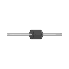
The Dioda Schottky (Manufacturer: OOOT, Part ID: 90QE9Q) is a semiconductor device designed to allow current to flow in one direction with minimal forward voltage drop and high-speed switching capabilities. Its unique construction, utilizing a metal-semiconductor junction, makes it highly efficient for applications requiring low power loss and fast response times.

Explore Projects Built with Dioda schottky

Use Cirkit Designer to design, explore, and prototype these projects online. Some projects support real-time simulation. Click "Open Project" to start designing instantly!
Rectifier Diode and LED Circuit with Rocker Switch Control
Image of hypihygi innovations: A project utilizing Dioda schottky in a practical application
This circuit appears to be a simple power supply circuit with a protection diode and an LED indicator. The diode ensures current flows in only one direction, protecting the circuit from reverse polarity damage. A rocker switch is used to control the power to the LED, which likely serves as an indicator for when the power is on.
Cirkit Designer LogoOpen Project in Cirkit Designer
Diode and Capacitor-Based Voltage Regulation Circuit
Image of Pavetra#2: A project utilizing Dioda schottky in a practical application
This circuit is a complex network of diodes and electrolytic capacitors connected to two terminal PCB 2-pin connectors. The diodes are arranged in a series-parallel configuration, while the capacitors are connected in a manner that suggests filtering or energy storage purposes. The overall design appears to be aimed at rectification and smoothing of an input signal.
Cirkit Designer LogoOpen Project in Cirkit Designer
Solar-Powered LED Illumination System with Arduino Control
Image of Smart Street Light: A project utilizing Dioda schottky in a practical application
This circuit is a solar-powered control system with light detection and actuation capabilities. It uses a solar panel to charge a battery and an Arduino UNO to monitor light levels via photodiodes and control high-power LEDs and a servomotor through a Darlington Driver. The system's functionality is determined by the embedded code running on the Arduino.
Cirkit Designer LogoOpen Project in Cirkit Designer
Solar-Powered LED Light with Battery Charging and Light Sensing
Image of ebt: A project utilizing Dioda schottky in a practical application
This circuit is a solar-powered battery charging and LED lighting system. The solar cell charges a 18650 Li-ion battery through a TP4056 charging module, which also powers a 7805 voltage regulator to provide a stable 5V output. A photocell and MOSFET control the power to a high-power LED, allowing it to turn on or off based on ambient light conditions.
Cirkit Designer LogoOpen Project in Cirkit Designer

Explore Projects Built with Dioda schottky

Use Cirkit Designer to design, explore, and prototype these projects online. Some projects support real-time simulation. Click "Open Project" to start designing instantly!
Image of hypihygi innovations: A project utilizing Dioda schottky in a practical application
Rectifier Diode and LED Circuit with Rocker Switch Control
This circuit appears to be a simple power supply circuit with a protection diode and an LED indicator. The diode ensures current flows in only one direction, protecting the circuit from reverse polarity damage. A rocker switch is used to control the power to the LED, which likely serves as an indicator for when the power is on.
Cirkit Designer LogoOpen Project in Cirkit Designer
Image of Pavetra#2: A project utilizing Dioda schottky in a practical application
Diode and Capacitor-Based Voltage Regulation Circuit
This circuit is a complex network of diodes and electrolytic capacitors connected to two terminal PCB 2-pin connectors. The diodes are arranged in a series-parallel configuration, while the capacitors are connected in a manner that suggests filtering or energy storage purposes. The overall design appears to be aimed at rectification and smoothing of an input signal.
Cirkit Designer LogoOpen Project in Cirkit Designer
Image of Smart Street Light: A project utilizing Dioda schottky in a practical application
Solar-Powered LED Illumination System with Arduino Control
This circuit is a solar-powered control system with light detection and actuation capabilities. It uses a solar panel to charge a battery and an Arduino UNO to monitor light levels via photodiodes and control high-power LEDs and a servomotor through a Darlington Driver. The system's functionality is determined by the embedded code running on the Arduino.
Cirkit Designer LogoOpen Project in Cirkit Designer
Image of ebt: A project utilizing Dioda schottky in a practical application
Solar-Powered LED Light with Battery Charging and Light Sensing
This circuit is a solar-powered battery charging and LED lighting system. The solar cell charges a 18650 Li-ion battery through a TP4056 charging module, which also powers a 7805 voltage regulator to provide a stable 5V output. A photocell and MOSFET control the power to a high-power LED, allowing it to turn on or off based on ambient light conditions.
Cirkit Designer LogoOpen Project in Cirkit Designer

Common Applications and Use Cases

  • Power rectification in power supplies
  • High-frequency switching circuits
  • Voltage clamping and protection
  • RF and microwave applications
  • Solar panel bypass diodes
  • Low-voltage, high-efficiency DC-DC converters

Technical Specifications

Key Technical Details

  • Forward Voltage Drop (Vf): 0.2V to 0.45V (typical, depending on current)
  • Maximum Reverse Voltage (Vr): 90V
  • Maximum Forward Current (If): 9A
  • Reverse Leakage Current (Ir): ≤ 1mA at Vr = 90V
  • Junction Temperature Range (Tj): -55°C to +150°C
  • Switching Speed: < 10ns
  • Package Type: TO-220

Pin Configuration and Descriptions

The Dioda Schottky (90QE9Q) is typically housed in a TO-220 package with three pins. Below is the pin configuration:

Pin Number Pin Name Description
1 Anode Positive terminal for current flow
2 Cathode Negative terminal for current flow
3 Cathode (Tab) Connected to the cathode, used for heat dissipation

Usage Instructions

How to Use the Component in a Circuit

  1. Polarity Matters: Ensure the anode is connected to the positive side of the circuit and the cathode to the negative side. Reversing the polarity will block current flow.
  2. Heat Dissipation: The TO-220 package includes a metal tab for heat dissipation. Use a heatsink if the diode operates at high currents to prevent overheating.
  3. Voltage Ratings: Do not exceed the maximum reverse voltage (90V) to avoid breakdown.
  4. Current Ratings: Ensure the forward current does not exceed 9A to prevent damage.
  5. Bypass Applications: In solar panels, connect the diode in parallel with the panel to prevent reverse current during low light conditions.

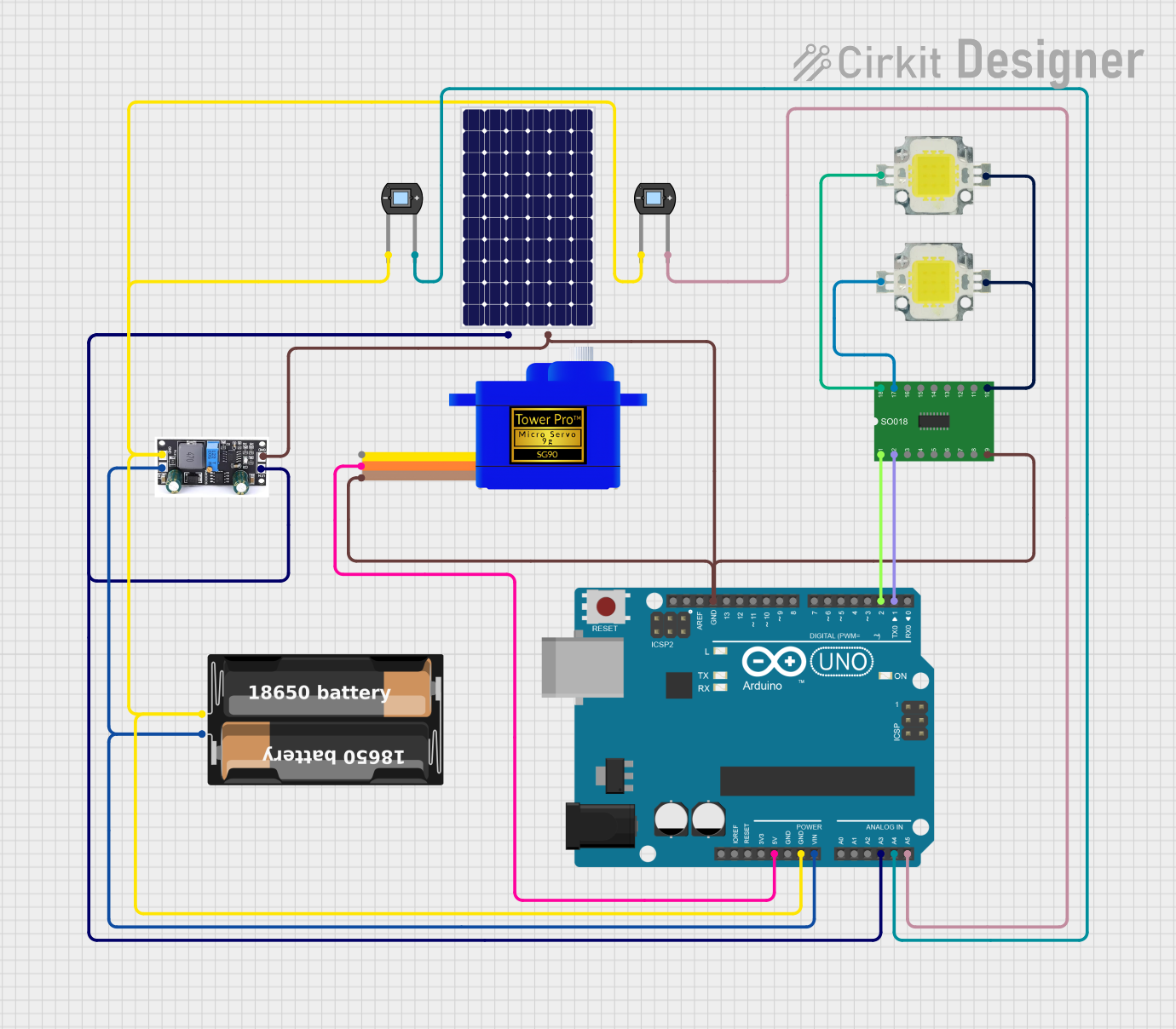
Example Circuit with Arduino UNO

The Dioda Schottky can be used in an Arduino-based DC motor driver circuit to protect against back EMF. Below is an example:

Circuit Description

  • The Schottky diode is placed across the motor terminals to prevent voltage spikes from damaging the Arduino or motor driver.

Code Example

// Example code for controlling a DC motor with Arduino UNO
// The Schottky diode protects against back EMF from the motor.

const int motorPin = 9; // PWM pin connected to motor driver

void setup() {
  pinMode(motorPin, OUTPUT); // Set motor pin as output
}

void loop() {
  analogWrite(motorPin, 128); // Run motor at 50% speed
  delay(5000);                // Run for 5 seconds
  analogWrite(motorPin, 0);   // Stop motor
  delay(2000);                // Wait for 2 seconds
}

Important Considerations and Best Practices

  • Thermal Management: Always monitor the diode's temperature during operation. Use a heatsink or thermal paste if necessary.
  • Parasitic Capacitance: In high-frequency circuits, consider the diode's parasitic capacitance, as it may affect performance.
  • Parallel Operation: When using multiple diodes in parallel, ensure proper current sharing by adding small resistors in series with each diode.

Troubleshooting and FAQs

Common Issues and Solutions

Issue Possible Cause Solution
Diode overheating Exceeding current or poor heat dissipation Use a heatsink or reduce the current load.
No current flow in the circuit Incorrect polarity connection Verify the anode and cathode connections.
High reverse leakage current Operating near maximum reverse voltage Reduce the reverse voltage or check for damaged diode.
Circuit not functioning as expected Faulty or damaged diode Test the diode with a multimeter and replace if necessary.

FAQs

  1. Can I use the Dioda Schottky for AC rectification?

    • Yes, but ensure the reverse voltage rating is sufficient for the peak AC voltage.
  2. What makes a Schottky diode different from a regular diode?

    • Schottky diodes have a lower forward voltage drop and faster switching speeds compared to regular silicon diodes.
  3. How do I test if the diode is working?

    • Use a multimeter in diode mode. Connect the positive lead to the anode and the negative lead to the cathode. A forward voltage drop of ~0.2V to 0.45V indicates a functional diode.
  4. Can I use this diode in high-frequency circuits?

    • Yes, the Dioda Schottky is ideal for high-frequency applications due to its fast switching speed.

By following this documentation, you can effectively integrate the Dioda Schottky (90QE9Q) into your electronic projects for efficient and reliable performance.