
How to Use LS35-12: Examples, Pinouts, and Specs
 Design with LS35-12 in Cirkit Designer
Introduction
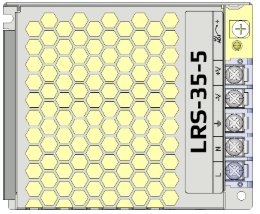
The LS35-12 is a compact, low-profile switching power supply designed to deliver a stable 12V DC output with a maximum current of 2.9A. Its robust design includes built-in over-voltage and short-circuit protection, ensuring reliable operation and safeguarding connected devices. This power supply is ideal for powering LED strips, small motors, sensors, and other low-power electronic devices. Its compact size and high efficiency make it a popular choice for both hobbyist and professional applications.
Explore Projects Built with LS35-12
 Open Project in Cirkit Designer
 Open Project in Cirkit Designer
 Open Project in Cirkit Designer
 Open Project in Cirkit Designer
Explore Projects Built with LS35-12
Open Project in Cirkit DesignerOpen Project in Cirkit DesignerOpen Project in Cirkit DesignerOpen Project in Cirkit DesignerCommon Applications
- Powering LED strips and lighting systems
- Driving small DC motors
- Supplying power to sensors and microcontrollers
- General-purpose low-power DC applications
Technical Specifications
Key Specifications
| Parameter | Value |
|---|---|
| Input Voltage Range | 85-264V AC or 120-370V DC |
| Output Voltage | 12V DC |
| Maximum Output Current | 2.9A |
| Output Power | 35W |
| Efficiency | Up to 85% |
| Protection Features | Over-voltage, short-circuit |
| Operating Temperature | -20°C to +70°C |
| Dimensions | 99mm x 82mm x 30mm |
| Weight | ~200g |
Pin Configuration and Descriptions
The LS35-12 has a simple terminal block for input and output connections. Below is the pin configuration:
Input Terminals
| Pin Name | Description |
|---|---|
| L | Live AC input (85-264V AC) |
| N | Neutral AC input |
| FG | Frame Ground (Earth connection) |
Output Terminals
| Pin Name | Description |
|---|---|
| V+ | Positive DC output (12V) |
| V- | Negative DC output (Ground) |
Usage Instructions
How to Use the LS35-12 in a Circuit
Input Connection:
- Connect the AC mains supply to the
L(Live) andN(Neutral) terminals. - Ensure the
FG(Frame Ground) terminal is connected to the earth ground for safety.
- Connect the AC mains supply to the
Output Connection:
- Connect the load (e.g., LED strip, motor) to the
V+andV-terminals. - Ensure the load does not exceed the maximum output current of 2.9A.
- Connect the load (e.g., LED strip, motor) to the
Power On:
- After verifying all connections, power on the AC mains supply.
- The LS35-12 will provide a stable 12V DC output to the connected load.
Important Considerations
- Load Requirements: Ensure the total load does not exceed 35W (12V x 2.9A). Overloading may trigger the protection features or damage the power supply.
- Ventilation: Install the LS35-12 in a well-ventilated area to prevent overheating.
- Safety: Always disconnect the power supply from the mains before making any wiring changes.
- Polarity: Double-check the polarity of the output connections to avoid damaging the connected devices.
Example: Powering an Arduino UNO
The LS35-12 can be used to power an Arduino UNO via its DC barrel jack or VIN pin. Below is an example setup:
- Connect the
V+terminal of the LS35-12 to the Arduino's VIN pin or DC barrel jack (center pin). - Connect the
V-terminal of the LS35-12 to the Arduino's GND pin or barrel jack outer sleeve.
Sample Arduino Code for Testing
// This code blinks an LED connected to pin 13 of the Arduino UNO.
// Ensure the LS35-12 is properly connected to the Arduino's VIN and GND pins.

void setup() {
  pinMode(13, OUTPUT); // Set pin 13 as an output
}

void loop() {
  digitalWrite(13, HIGH); // Turn the LED on
  delay(1000);            // Wait for 1 second
  digitalWrite(13, LOW);  // Turn the LED off
  delay(1000);            // Wait for 1 second
}
Troubleshooting and FAQs
Common Issues and Solutions
| Issue | Possible Cause | Solution |
|---|---|---|
| No output voltage | Incorrect input wiring | Verify AC input connections to L and N. |
| Output voltage fluctuates | Overloaded power supply | Reduce the load to within 35W limit. |
| Power supply overheats | Poor ventilation or excessive load | Ensure proper airflow and reduce load. |
| Connected device not working | Incorrect polarity on output terminals | Verify V+ and V- connections. |
FAQs
Can the LS35-12 be used with a 24V device?
- No, the LS35-12 provides a fixed 12V output and is not suitable for 24V devices.
What happens if the load exceeds 2.9A?
- The LS35-12 has built-in over-current protection. If the load exceeds 2.9A, the power supply will shut down to protect itself and the connected devices.
Is the LS35-12 suitable for outdoor use?
- No, the LS35-12 is not weatherproof. It should be used in a dry, indoor environment.
Can I use the LS35-12 to charge a 12V battery?
- The LS35-12 is not designed as a battery charger. Use a dedicated 12V battery charger for this purpose.
By following these guidelines and best practices, the LS35-12 can provide reliable and efficient power for a wide range of electronic applications.