Cirkit Designer Logo
Cirkit Designer
Your all-in-one circuit design IDE
Home / 
Component Documentation

How to Use iBIT: Examples, Pinouts, and Specs

Image of iBIT
Cirkit Designer LogoDesign with iBIT in Cirkit Designer

Introduction

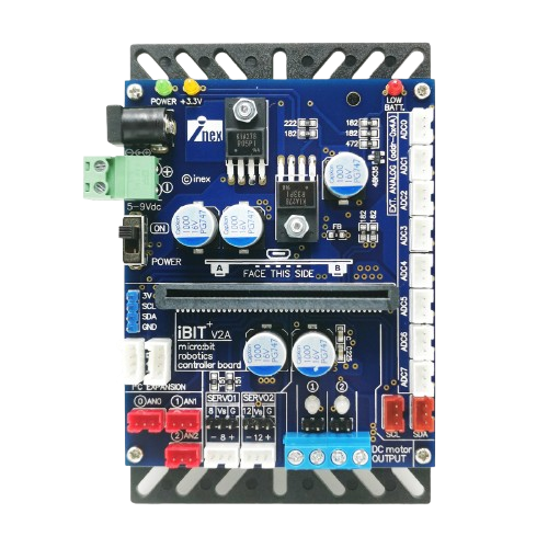
The iBIT, manufactured by INEX (Part ID: Board), is a compact and programmable microcontroller designed specifically for educational purposes and prototyping. It features built-in sensors and connectivity options, making it an ideal choice for beginners and experienced developers alike. The iBIT simplifies the process of integrating hardware and software, enabling users to focus on innovation and creativity.

Explore Projects Built with iBIT

Use Cirkit Designer to design, explore, and prototype these projects online. Some projects support real-time simulation. Click "Open Project" to start designing instantly!
ESP32-Controlled Multi-Axis Actuator System with Orientation Sensing and Light Detection
Image of Auto_Level_Table: A project utilizing iBIT in a practical application
This circuit features an ESP32 S3 N32R8V microcontroller interfaced with multiple IBT-2 H-Bridge Motor Drivers to control several Linear Actuators, and it receives input from KY-018 LDR Photo Resistors and Pushbuttons. The ESP32 is powered by a 5V supply from an Adafruit MPM3610 5V Buck Converter, while the Linear Actuators and Motor Drivers are powered by a 12V 7Ah battery. Additionally, the ESP32 communicates with an Adafruit BNO085 9-DOF Orientation IMU Fusion Breakout for orientation sensing.
Cirkit Designer LogoOpen Project in Cirkit Designer
ESP32 and Logic Level Converter-Based Wi-Fi Controlled Interface
Image of Toshiba AC ESP32 devkit v1: A project utilizing iBIT in a practical application
This circuit features an ESP32 Devkit V1 microcontroller connected to a Bi-Directional Logic Level Converter, which facilitates voltage level shifting between the ESP32 and external components. The ESP32 is powered through its VIN pin via an alligator clip cable, and the logic level converter is connected to various pins on the ESP32 to manage different voltage levels for communication.
Cirkit Designer LogoOpen Project in Cirkit Designer
Arduino UNO-Based Smart Environmental Monitoring and Control System with Bluetooth Connectivity
Image of home automation: A project utilizing iBIT in a practical application
This is a smart control system utilizing an Arduino UNO to interface with Bluetooth communication, light, temperature, humidity, and motion sensors, and to control a relay module for a bulb and a fan. It features a solar-powered charging circuit for energy management and a power inverter to supply AC power to the bulb.
Cirkit Designer LogoOpen Project in Cirkit Designer
Beelink Mini S12 N95 and Arduino UNO Based Fingerprint Authentication System with ESP32 CAM
Image of design 3: A project utilizing iBIT in a practical application
This circuit features a Beelink MINI S12 N95 computer connected to a 7-inch display via HDMI for video output and two USB connections for power and touch screen functionality. An Arduino UNO is interfaced with a fingerprint scanner for biometric input. The Beelink MINI S12 N95 is powered by a PC power supply, which in turn is connected to a 240V power source. Additionally, an ESP32 CAM module is powered and programmed via a USB plug and an FTDI programmer, respectively, for wireless camera capabilities.
Cirkit Designer LogoOpen Project in Cirkit Designer

Explore Projects Built with iBIT

Use Cirkit Designer to design, explore, and prototype these projects online. Some projects support real-time simulation. Click "Open Project" to start designing instantly!
Image of Auto_Level_Table: A project utilizing iBIT in a practical application
ESP32-Controlled Multi-Axis Actuator System with Orientation Sensing and Light Detection
This circuit features an ESP32 S3 N32R8V microcontroller interfaced with multiple IBT-2 H-Bridge Motor Drivers to control several Linear Actuators, and it receives input from KY-018 LDR Photo Resistors and Pushbuttons. The ESP32 is powered by a 5V supply from an Adafruit MPM3610 5V Buck Converter, while the Linear Actuators and Motor Drivers are powered by a 12V 7Ah battery. Additionally, the ESP32 communicates with an Adafruit BNO085 9-DOF Orientation IMU Fusion Breakout for orientation sensing.
Cirkit Designer LogoOpen Project in Cirkit Designer
Image of Toshiba AC ESP32 devkit v1: A project utilizing iBIT in a practical application
ESP32 and Logic Level Converter-Based Wi-Fi Controlled Interface
This circuit features an ESP32 Devkit V1 microcontroller connected to a Bi-Directional Logic Level Converter, which facilitates voltage level shifting between the ESP32 and external components. The ESP32 is powered through its VIN pin via an alligator clip cable, and the logic level converter is connected to various pins on the ESP32 to manage different voltage levels for communication.
Cirkit Designer LogoOpen Project in Cirkit Designer
Image of home automation: A project utilizing iBIT in a practical application
Arduino UNO-Based Smart Environmental Monitoring and Control System with Bluetooth Connectivity
This is a smart control system utilizing an Arduino UNO to interface with Bluetooth communication, light, temperature, humidity, and motion sensors, and to control a relay module for a bulb and a fan. It features a solar-powered charging circuit for energy management and a power inverter to supply AC power to the bulb.
Cirkit Designer LogoOpen Project in Cirkit Designer
Image of design 3: A project utilizing iBIT in a practical application
Beelink Mini S12 N95 and Arduino UNO Based Fingerprint Authentication System with ESP32 CAM
This circuit features a Beelink MINI S12 N95 computer connected to a 7-inch display via HDMI for video output and two USB connections for power and touch screen functionality. An Arduino UNO is interfaced with a fingerprint scanner for biometric input. The Beelink MINI S12 N95 is powered by a PC power supply, which in turn is connected to a 240V power source. Additionally, an ESP32 CAM module is powered and programmed via a USB plug and an FTDI programmer, respectively, for wireless camera capabilities.
Cirkit Designer LogoOpen Project in Cirkit Designer

Common Applications and Use Cases

  • Robotics and automation projects
  • STEM education and hands-on learning
  • IoT (Internet of Things) prototyping
  • Sensor-based data collection and analysis
  • Interactive art and design installations

Technical Specifications

The iBIT microcontroller is equipped with a variety of features to support diverse applications. Below are its key technical specifications:

General Specifications

Parameter Value
Microcontroller ARM Cortex-M0+
Operating Voltage 3.3V
Input Voltage Range 3.3V - 5V
Connectivity Bluetooth Low Energy (BLE)
Built-in Sensors Light, Temperature, Accelerometer
GPIO Pins 6 (Digital/Analog)
Programming Interface USB Type-C
Dimensions 50mm x 25mm x 10mm

Pin Configuration and Descriptions

Pin Number Pin Name Description
1 GND Ground
2 VCC Power supply input (3.3V - 5V)
3 GPIO1 General-purpose I/O pin (Digital/Analog)
4 GPIO2 General-purpose I/O pin (Digital/Analog)
5 GPIO3 General-purpose I/O pin (Digital/Analog)
6 GPIO4 General-purpose I/O pin (Digital/Analog)
7 GPIO5 General-purpose I/O pin (Digital/Analog)
8 GPIO6 General-purpose I/O pin (Digital/Analog)
9 TX UART Transmit
10 RX UART Receive

Usage Instructions

The iBIT microcontroller is designed for ease of use, making it suitable for both beginners and advanced users. Follow the steps below to get started:

Step 1: Powering the iBIT

  • Connect the iBIT to a power source using the USB Type-C port or an external 3.3V - 5V power supply.
  • Ensure the power supply is stable to avoid damaging the board.

Step 2: Programming the iBIT

  • The iBIT can be programmed using popular IDEs such as Arduino IDE or MicroPython.
  • Install the necessary drivers and libraries for the iBIT from the INEX website.
  • Select the appropriate board and port in your IDE before uploading code.

Step 3: Connecting Sensors and Actuators

  • Use the GPIO pins to connect external sensors, actuators, or other peripherals.
  • Refer to the pin configuration table to identify the correct pins for your connections.

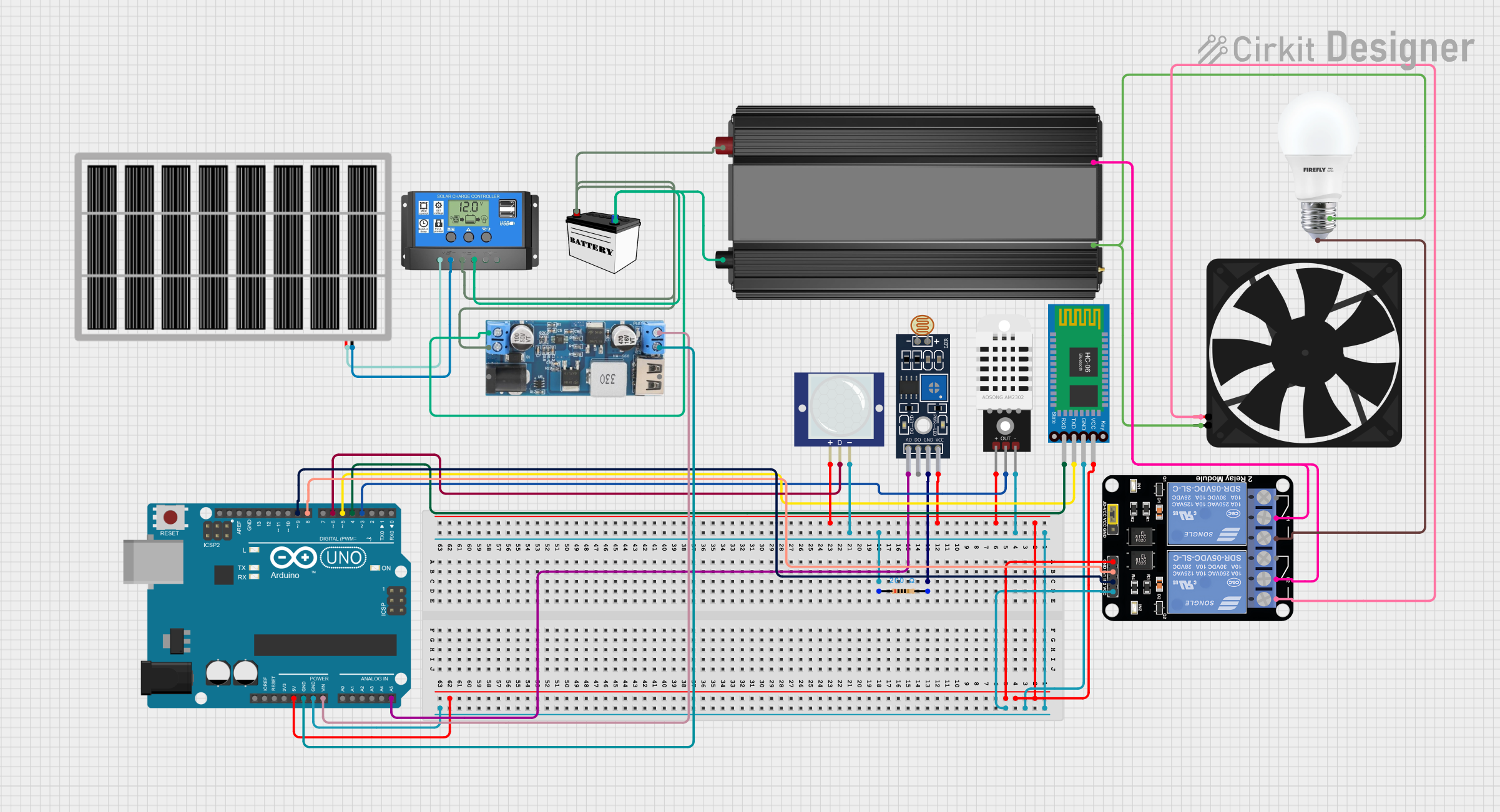
Example: Using iBIT with Arduino UNO

Below is an example of how to read data from the built-in temperature sensor and display it on the serial monitor:

// Include necessary libraries
#include <Wire.h>

// Define the I2C address for the temperature sensor
#define TEMP_SENSOR_ADDR 0x48

void setup() {
  Serial.begin(9600); // Initialize serial communication at 9600 baud
  Wire.begin();       // Initialize I2C communication
  Serial.println("iBIT Temperature Sensor Example");
}

void loop() {
  Wire.beginTransmission(TEMP_SENSOR_ADDR); // Start communication with sensor
  Wire.write(0x00);                         // Request temperature data
  Wire.endTransmission();

  Wire.requestFrom(TEMP_SENSOR_ADDR, 2);    // Request 2 bytes of data
  if (Wire.available() == 2) {
    int tempData = Wire.read() << 8 | Wire.read(); // Combine bytes into a value
    float temperature = tempData * 0.0625;        // Convert to Celsius
    Serial.print("Temperature: ");
    Serial.print(temperature);
    Serial.println(" °C");
  }

  delay(1000); // Wait 1 second before reading again
}

Best Practices

  • Avoid exceeding the voltage and current ratings of the iBIT to prevent damage.
  • Use proper pull-up or pull-down resistors when connecting external components.
  • Keep the iBIT firmware updated to ensure compatibility with the latest features.

Troubleshooting and FAQs

Common Issues and Solutions

  1. The iBIT is not detected by the computer.

    • Ensure the USB cable is properly connected and functional.
    • Check if the necessary drivers are installed on your computer.
    • Try using a different USB port or cable.
  2. The iBIT is not responding to uploaded code.

    • Verify that the correct board and port are selected in your IDE.
    • Check for syntax errors or missing libraries in your code.
    • Reset the iBIT by pressing the onboard reset button.
  3. Sensors are not providing accurate readings.

    • Ensure the sensors are properly connected and not obstructed.
    • Calibrate the sensors if necessary, following the manufacturer's guidelines.
    • Avoid exposing the sensors to extreme conditions beyond their operating range.

FAQs

Q: Can the iBIT be powered using batteries?
A: Yes, the iBIT can be powered using a 3.3V - 5V battery pack. Ensure the battery voltage is within the specified range.

Q: Is the iBIT compatible with other microcontrollers?
A: Yes, the iBIT can communicate with other microcontrollers via UART, I2C, or GPIO pins.

Q: Where can I find additional resources for the iBIT?
A: Visit the INEX website for documentation, tutorials, and firmware updates.

By following this documentation, you can effectively utilize the iBIT microcontroller for your projects and experiments.