How to Use VSD: Examples, Pinouts, and Specs
Introduction
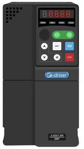
The Voltage Source Device (VSD), manufactured by Motorelli with part ID AD1000, is a reliable and efficient electronic component designed to provide a stable and specific voltage output to a circuit. It is commonly used to power electronic components or systems that require a consistent voltage supply. The VSD is ideal for applications in embedded systems, industrial automation, and prototyping environments.
Explore Projects Built with VSD
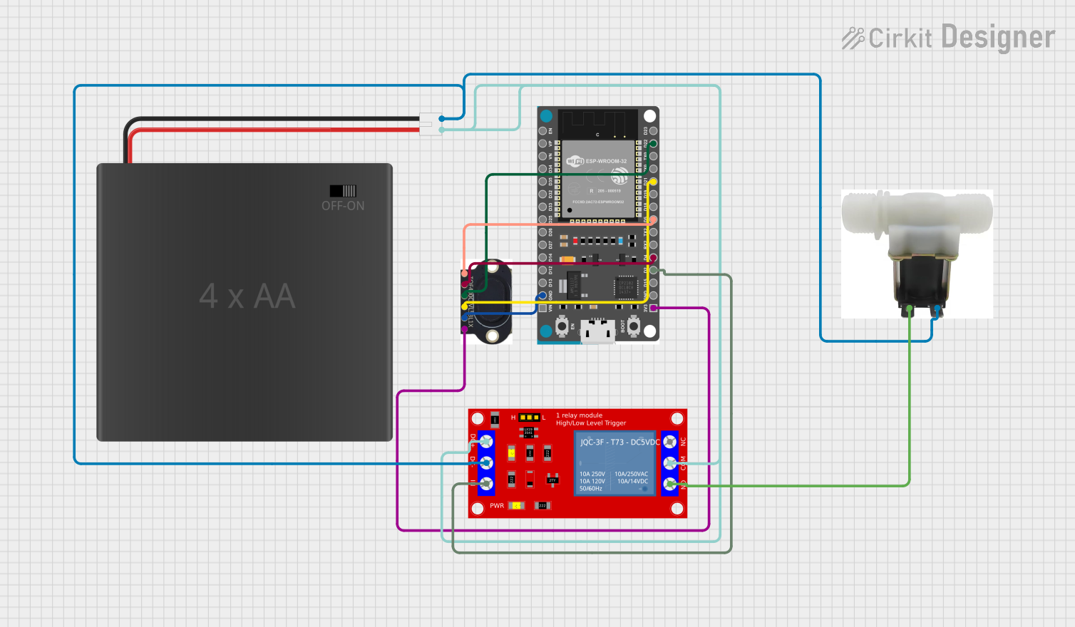
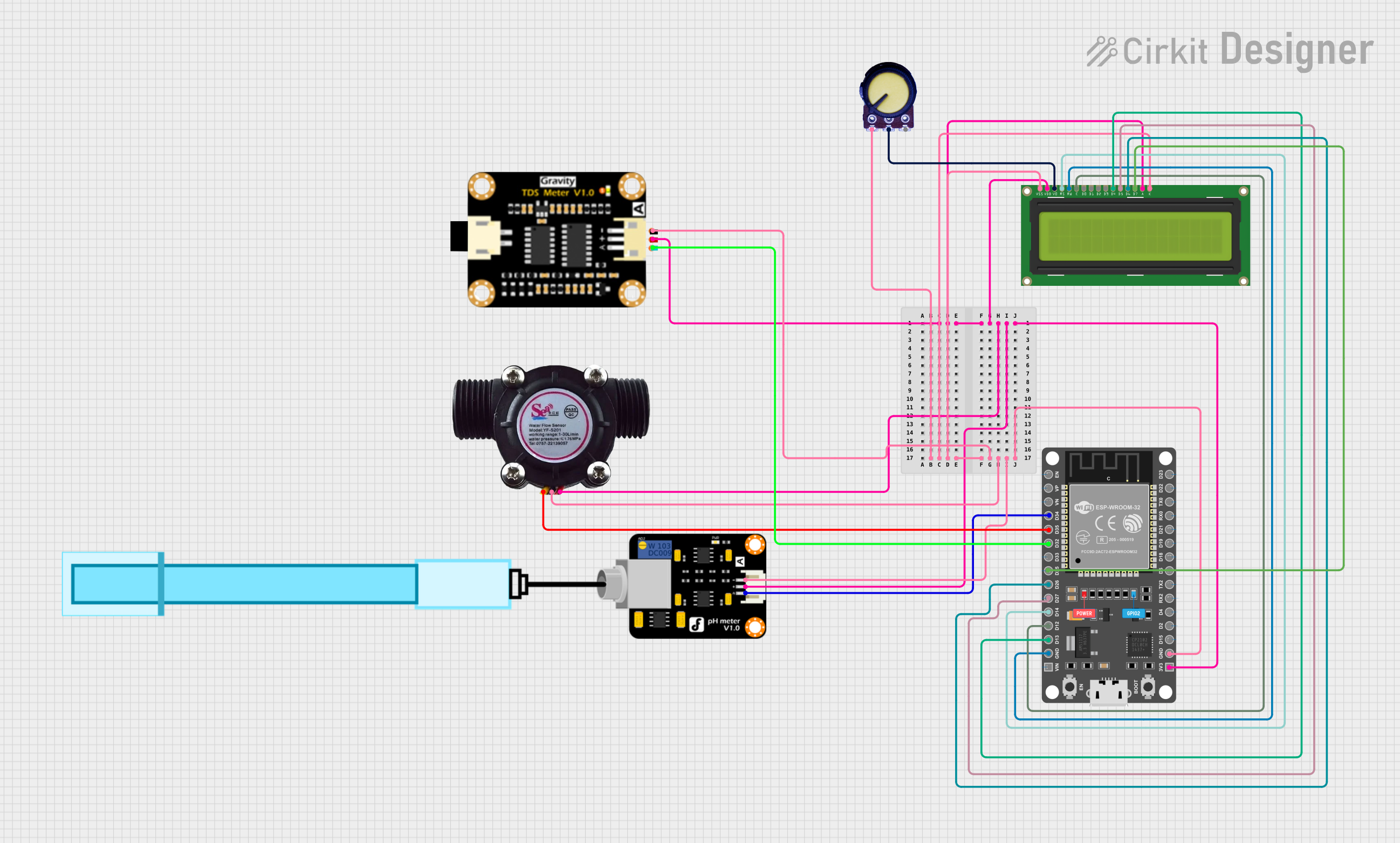
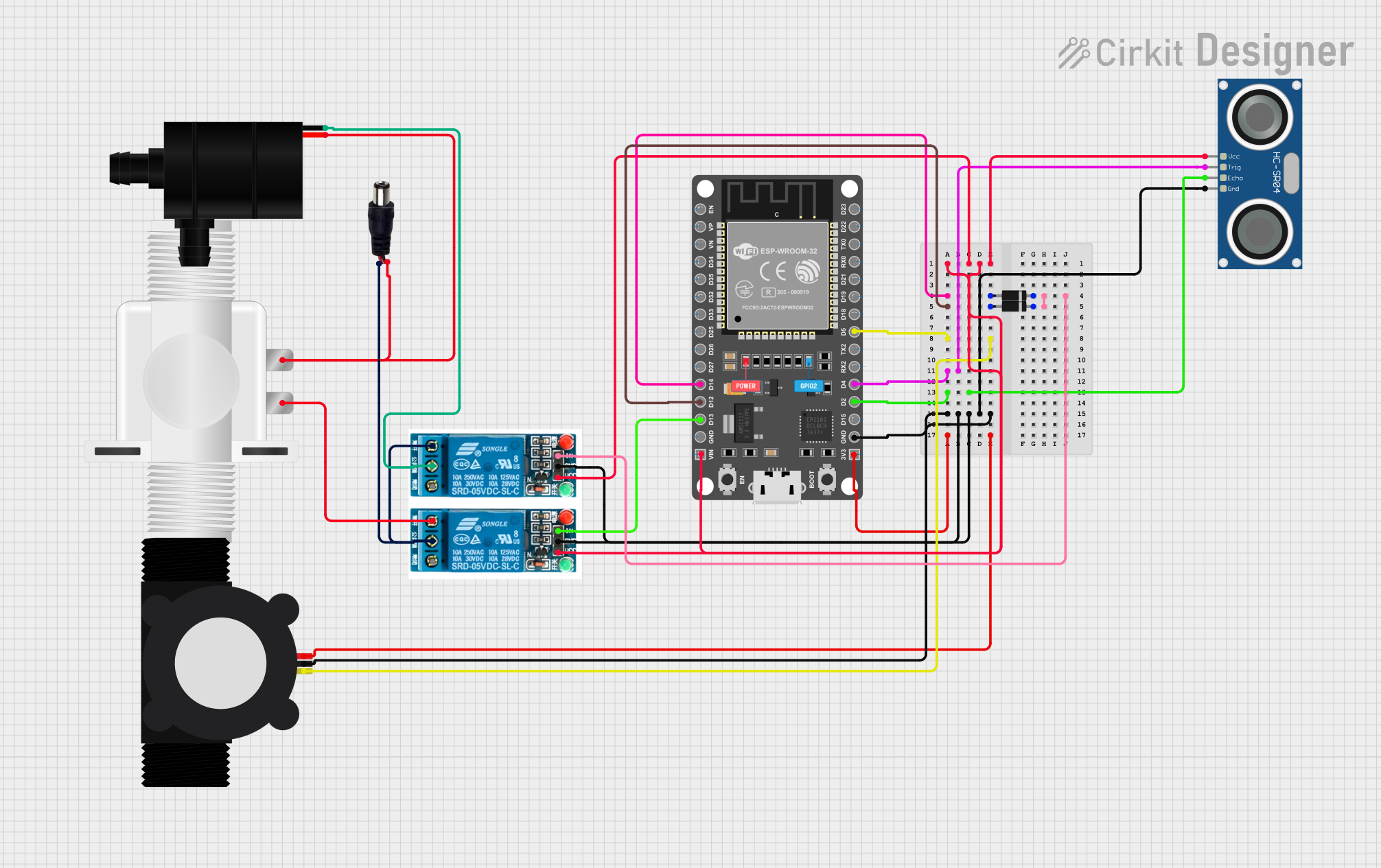
Explore Projects Built with VSD
Common Applications and Use Cases
- Powering microcontrollers, sensors, and actuators in embedded systems
- Providing a stable voltage source for industrial control systems
- Supplying power to prototyping boards and development kits
- Voltage regulation in battery-powered devices
- Laboratory testing and experimentation
Technical Specifications
The following table outlines the key technical details of the Motorelli AD1000 VSD:
| Parameter | Value |
|---|---|
| Input Voltage Range | 6V to 24V |
| Output Voltage | 5V ± 0.1V |
| Maximum Output Current | 1A |
| Efficiency | Up to 90% |
| Operating Temperature | -20°C to +70°C |
| Dimensions | 25mm x 15mm x 10mm |
| Weight | 10g |
Pin Configuration and Descriptions
The AD1000 VSD has three pins, as described in the table below:
| Pin | Name | Description |
|---|---|---|
| 1 | VIN | Input voltage pin (6V to 24V) |
| 2 | GND | Ground connection |
| 3 | VOUT | Regulated output voltage pin (5V ± 0.1V) |
Usage Instructions
How to Use the Component in a Circuit
Connect the Input Voltage (VIN):
Supply a DC voltage between 6V and 24V to the VIN pin. Ensure the input voltage is within the specified range to avoid damaging the device.Connect the Ground (GND):
Connect the GND pin to the ground of your circuit. This establishes a common reference point for the voltage source.Connect the Output Voltage (VOUT):
Use the VOUT pin to power your circuit or device. The VSD will provide a stable 5V output.Verify Connections:
Double-check all connections before powering the circuit to ensure proper operation.
Important Considerations and Best Practices
- Input Voltage Range: Always ensure the input voltage is within the specified range (6V to 24V). Exceeding this range may damage the VSD.
- Current Limitation: The maximum output current is 1A. Avoid connecting loads that draw more than 1A to prevent overheating or failure.
- Heat Dissipation: If the VSD operates near its maximum current rating for extended periods, consider adding a heatsink or ensuring proper ventilation.
- Polarity Protection: Ensure correct polarity when connecting the input voltage. Reversing the polarity may damage the device.
Example: Using the VSD with an Arduino UNO
The AD1000 VSD can be used to power an Arduino UNO by providing a stable 5V supply. Below is an example circuit and code:
Circuit Connections
- Connect the VIN pin of the VSD to a 9V battery.
- Connect the GND pin of the VSD to the GND of the Arduino UNO.
- Connect the VOUT pin of the VSD to the 5V pin of the Arduino UNO.
Arduino Code Example
// Example code to blink an LED using an Arduino UNO powered by the AD1000 VSD

const int ledPin = 13; // Pin connected to the onboard LED

void setup() {
  pinMode(ledPin, OUTPUT); // Set the LED pin as an output
}

void loop() {
  digitalWrite(ledPin, HIGH); // Turn the LED on
  delay(1000);                // Wait for 1 second
  digitalWrite(ledPin, LOW);  // Turn the LED off
  delay(1000);                // Wait for 1 second
}
Troubleshooting and FAQs
Common Issues and Solutions
No Output Voltage:
- Cause: Input voltage is not within the specified range.
- Solution: Verify that the input voltage is between 6V and 24V.
Overheating:
- Cause: Excessive current draw or poor ventilation.
- Solution: Ensure the load does not exceed 1A. Improve ventilation or add a heatsink.
Fluctuating Output Voltage:
- Cause: Unstable input voltage or excessive load.
- Solution: Use a stable DC power source and ensure the load is within the specified limits.
Device Not Powering On:
- Cause: Incorrect wiring or reversed polarity.
- Solution: Double-check all connections and ensure correct polarity.
FAQs
Q: Can the AD1000 VSD be used with a 12V car battery?
A: Yes, the AD1000 VSD can be used with a 12V car battery as the input voltage is within the supported range (6V to 24V).
Q: Is the AD1000 VSD protected against short circuits?
A: No, the AD1000 VSD does not have built-in short-circuit protection. Avoid shorting the output pins to prevent damage.
Q: Can I use the AD1000 VSD to power a Raspberry Pi?
A: The AD1000 VSD can provide a stable 5V output, but ensure the total current draw of the Raspberry Pi and connected peripherals does not exceed 1A.
Q: What happens if I exceed the maximum input voltage?
A: Exceeding the input voltage range (24V) may permanently damage the VSD. Always use a regulated power source within the specified range.