How to Use VL53L1X: Examples, Pinouts, and Specs
Introduction
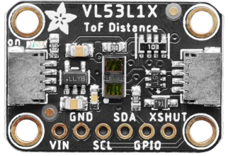
The VL53L1X is a time-of-flight (ToF) distance sensor manufactured by Adafruit (Part ID: 3967). It uses laser technology to measure distances with high accuracy and precision. This sensor can measure distances ranging from 30 mm to 4 meters, making it ideal for applications requiring precise distance measurements. Its compact size and low power consumption make it suitable for use in robotics, drones, automation systems, and proximity sensing.
Explore Projects Built with VL53L1X

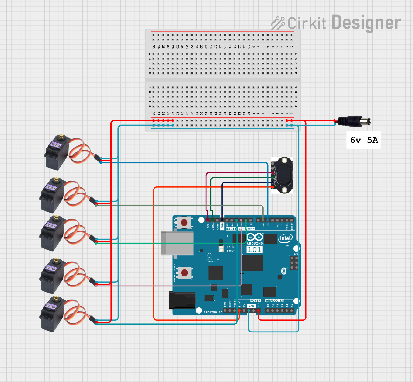

Explore Projects Built with VL53L1X
Common Applications
- Obstacle detection in robotics and drones
- Proximity sensing in automation systems
- Gesture recognition
- Distance measurement in industrial equipment
- Smart home devices (e.g., automatic doors, lighting systems)
Technical Specifications
The VL53L1X sensor offers advanced features and reliable performance. Below are its key technical specifications:
| Parameter | Value |
|---|---|
| Operating Voltage | 2.6V to 3.5V |
| Communication Interface | I²C |
| Measurement Range | 30 mm to 4 meters |
| Accuracy | ±1 mm (typical) |
| Field of View (FoV) | Programmable, up to 27° |
| Power Consumption | 20 mW (typical) |
| Operating Temperature | -20°C to +85°C |
| Dimensions | 4.9 mm x 2.5 mm x 1.56 mm |
Pin Configuration
The VL53L1X sensor module has the following pinout:
| Pin Name | Description |
|---|---|
| VIN | Power supply input (2.6V to 5V) |
| GND | Ground |
| SDA | I²C data line |
| SCL | I²C clock line |
| XSHUT | Shutdown pin (active low, optional) |
| GPIO1 | Interrupt output (optional) |
Usage Instructions
The VL53L1X sensor is easy to integrate into a circuit and communicate with using the I²C protocol. Below are the steps to use the sensor effectively:
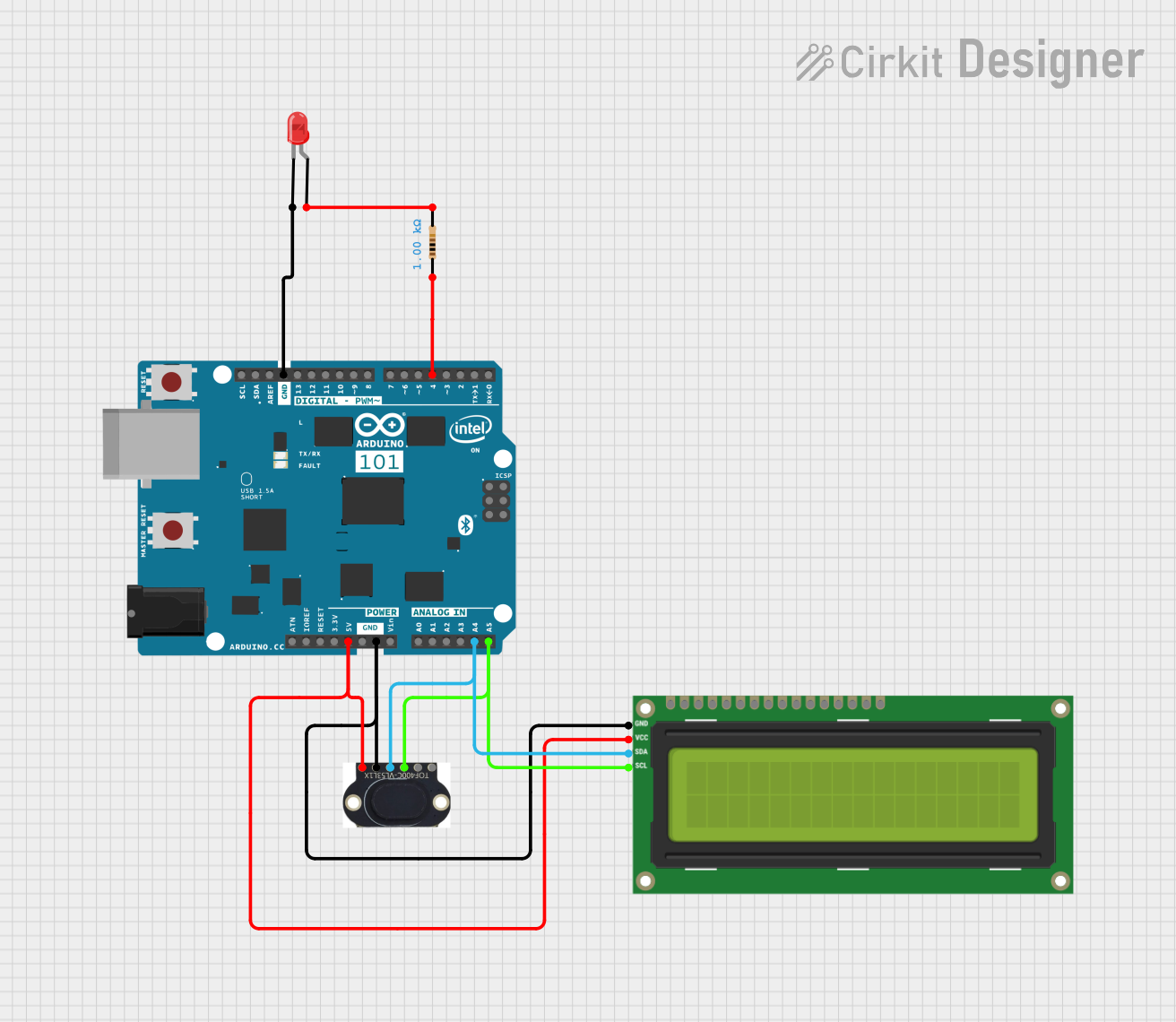
Connecting the VL53L1X to an Arduino UNO
Wiring: Connect the sensor to the Arduino UNO as follows:
VINto Arduino5VGNDto ArduinoGNDSDAto ArduinoA4(I²C data line)SCLto ArduinoA5(I²C clock line)- Optionally, connect
XSHUTandGPIO1to digital pins if needed.
Install the Library: Install the Adafruit VL53L1X library in the Arduino IDE:
- Go to Sketch > Include Library > Manage Libraries.
- Search for "Adafruit VL53L1X" and click Install.
Upload Example Code: Use the following example code to read distance measurements:
#include <Wire.h>
#include <Adafruit_VL53L1X.h>

// Create an instance of the VL53L1X sensor
Adafruit_VL53L1X vl53 = Adafruit_VL53L1X();

void setup() {
  Serial.begin(115200);
  while (!Serial) {
    delay(10); // Wait for Serial Monitor to open
  }

  // Initialize the sensor
  if (!vl53.begin()) {
    Serial.println("Failed to find VL53L1X sensor!");
    while (1) {
      delay(10); // Halt if sensor initialization fails
    }
  }
  Serial.println("VL53L1X sensor initialized!");

  // Set the distance mode (Short, Medium, or Long)
  vl53.setDistanceMode(VL53L1X::Long);
  // Set the timing budget (in milliseconds)
  vl53.setTimingBudget(50);
  // Start continuous measurements
  vl53.startContinuous();
}

void loop() {
  // Read the distance in millimeters
  uint16_t distance = vl53.read();
  if (distance != 0) {
    Serial.print("Distance: ");
    Serial.print(distance);
    Serial.println(" mm");
  } else {
    Serial.println("Error reading distance!");
  }
  delay(100); // Delay between readings
}
Important Considerations
- Power Supply: Ensure the sensor is powered within its operating voltage range (2.6V to 5V). Using a voltage regulator may be necessary for higher voltages.
- I²C Address: The default I²C address of the VL53L1X is
0x29. If multiple sensors are used, their addresses must be changed programmatically. - Field of View: The sensor's field of view can be adjusted programmatically to suit specific applications.
- Ambient Light: Avoid using the sensor in environments with excessive ambient light, as it may affect accuracy.
Troubleshooting and FAQs
Common Issues
Sensor Not Detected
- Cause: Incorrect wiring or I²C address conflict.
- Solution: Double-check the wiring and ensure the I²C address matches the one in the code.
Inaccurate Distance Measurements
- Cause: Reflective or transparent surfaces in the sensor's path.
- Solution: Use a matte surface for testing and avoid transparent or highly reflective objects.
Interference from Ambient Light
- Cause: Excessive ambient light affecting the laser.
- Solution: Shield the sensor from direct sunlight or bright light sources.
Sensor Initialization Fails
- Cause: Faulty sensor or incorrect library installation.
- Solution: Verify the library installation and try a different sensor module.
FAQs
Q: Can the VL53L1X measure distances beyond 4 meters?
A: No, the maximum range of the VL53L1X is 4 meters. For longer ranges, consider using a different sensor.
Q: How can I use multiple VL53L1X sensors on the same I²C bus?
A: Use the XSHUT pin to reset individual sensors and assign unique I²C addresses programmatically.
Q: What is the timing budget, and how does it affect performance?
A: The timing budget is the time the sensor spends on a single measurement. A longer timing budget improves accuracy but reduces the measurement rate.
Q: Can the VL53L1X detect transparent objects?
A: The sensor may struggle with transparent objects, as the laser may pass through them without reflecting back.
By following this documentation, users can effectively integrate and utilize the VL53L1X sensor in their projects.