How to Use USB Plug: Examples, Pinouts, and Specs
Introduction
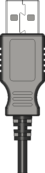
A USB (Universal Serial Bus) Plug is a standard connector used in a wide range of electronic devices for power delivery and data transfer. It has become ubiquitous in the digital age, connecting peripherals like smartphones, tablets, computers, cameras, and many other gadgets to each other or to power sources. USB plugs come in various forms, including Type-A, Type-B, Micro-USB, Mini-USB, and the newer Type-C, each with its own specific applications and design.
Explore Projects Built with USB Plug

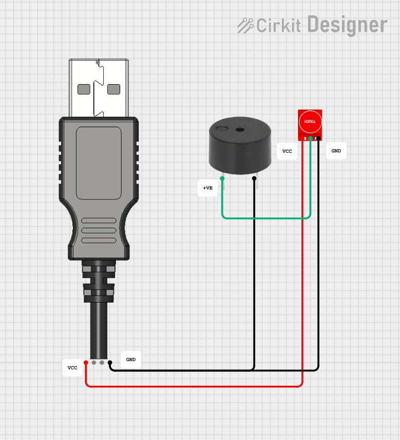


Explore Projects Built with USB Plug
Common Applications and Use Cases
- Charging electronic devices
- Transferring data between devices (e.g., syncing a smartphone with a computer)
- Connecting peripherals (e.g., printers, keyboards, mice) to computers
- Serving as a bridge in communication protocols (e.g., serial communication over USB)
Technical Specifications
Key Technical Details
| Specification | Description |
|---|---|
| Voltage | 5V standard (USB 2.0 and 3.0), 20V max (USB PD) |
| Current | Up to 500mA (USB 2.0), 900mA (USB 3.0), higher currents with USB PD |
| Data Transfer Rate | Up to 480 Mbps (USB 2.0), 5 Gbps (USB 3.0), 10 Gbps (USB 3.1 Gen 2), 20 Gbps (USB4) |
| Connector Types | Type-A, Type-B, Micro-USB, Mini-USB, Type-C |
Pin Configuration and Descriptions
USB Type-A
| Pin Number | Name | Description |
|---|---|---|
| 1 | VBUS | +5V Power |
| 2 | D- | Data Minus |
| 3 | D+ | Data Plus |
| 4 | GND | Ground |
USB Type-C
| Pin Number | Name | Description |
|---|---|---|
| A1-A12, B1-B12 | VBUS, GND, D+, D-, SBU, CC | Multiple functions including power, data, and configuration channels |
Usage Instructions
How to Use the USB Plug in a Circuit
- Identify the USB type: Determine the type of USB plug required for your application.
- Power connections: Connect the VBUS pin to a 5V power source and the GND pin to the ground.
- Data connections: For data transfer, connect the D+ and D- pins to the corresponding data lines on the device.
- Ensure correct orientation: USB plugs are keyed to fit in one way. For reversible plugs like USB Type-C, orientation is not an issue.
Important Considerations and Best Practices
- Power Limits: Do not exceed the current and voltage ratings of the USB specification to avoid damage.
- Data Integrity: Use shielded cables for data transfer to minimize interference.
- Hot-Plugging: USB supports hot-plugging, but ensure the device supports it as well to prevent data loss or damage.
- Cable Quality: Use cables with proper ratings, especially for fast charging or high-speed data transfer.
Troubleshooting and FAQs
Common Issues
- Device Not Recognized: Check the connection, try a different port or cable, and ensure drivers are up to date.
- Slow Charging: Verify that the power source and cable support the required current for fast charging.
- Data Transfer Errors: Use a shorter or higher-quality cable, and ensure there is no physical damage to the connectors.
Solutions and Tips
- Cleaning: Keep the USB ports and plugs clean and free from debris.
- Cable Management: Avoid bending cables sharply or coiling them too tightly to prevent internal damage.
- Port Wear: Repeated use can wear out USB ports. If connections become loose, consider port replacement.
FAQs
Q: Can I use any USB cable for data transfer? A: Not all USB cables are designed for data transfer. Some are charge-only. Ensure your cable supports data.
Q: What is USB PD? A: USB Power Delivery (USB PD) is a charging protocol that allows for higher power delivery over USB, up to 100W.
Q: How do I know if my device is USB 3.0 or 2.0? A: USB 3.0 ports and plugs are usually blue and have additional pins. Check your device's specifications for confirmation.
Q: Can I plug a USB 2.0 device into a USB 3.0 port? A: Yes, USB 3.0 is backward compatible with USB 2.0, though it will operate at USB 2.0 speeds.
Q: Why does my device charge faster with some chargers and not others? A: Charging speed can vary based on the charger's output capacity and whether it supports fast charging protocols compatible with your device.
Example Code for Arduino UNO
// This example assumes the use of a USB to Serial converter connected to an Arduino UNO.
// The Arduino will echo any data received from the USB connection back to the connected device.

void setup() {
  // Start serial communication at 9600 baud rate
  Serial.begin(9600);
}

void loop() {
  // Check if data is available to read
  if (Serial.available() > 0) {
    // Read the incoming byte
    char incomingByte = Serial.read();

    // Echo the byte back out through the serial (USB) connection
    Serial.write(incomingByte);
  }
}
Note: This code is for demonstration purposes and assumes the use of a USB to Serial converter that is compatible with the Arduino UNO. The Arduino itself does not have a USB host capability, so it cannot directly communicate with USB devices without additional hardware.