How to Use current to voltage converter: Examples, Pinouts, and Specs
Introduction
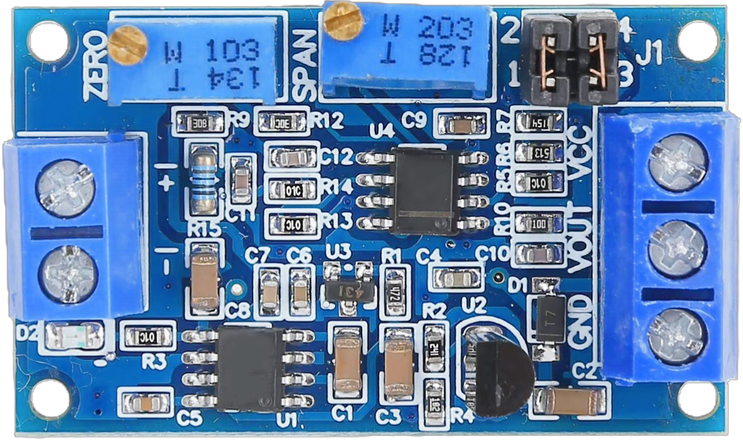
A current to voltage converter is an electronic device that converts an input current signal into a proportional output voltage signal. This component is widely used in measurement and control systems to interface current sources, such as sensors or transducers, with voltage-based devices like analog-to-digital converters (ADCs) or microcontrollers. By providing a linear relationship between current and voltage, it ensures accurate signal processing and compatibility between different systems.
Explore Projects Built with current to voltage converter


Explore Projects Built with current to voltage converter
Common Applications and Use Cases
- Interfacing 4-20 mA current loop sensors with voltage-based systems.
- Signal conditioning in industrial automation and process control.
- Analog signal processing in data acquisition systems.
- Current measurement in power electronics and motor control circuits.
Technical Specifications
Below are the general technical specifications for a typical current to voltage converter. Specific values may vary depending on the model or design.
Key Technical Details
- Input Current Range: 0 mA to 20 mA (typical), or 4 mA to 20 mA for industrial applications.
- Output Voltage Range: 0 V to 5 V or 0 V to 10 V (depending on configuration).
- Supply Voltage: 5 V, 12 V, or 24 V DC (depending on the design).
- Conversion Accuracy: ±0.1% to ±1% of full scale.
- Input Impedance: Low (to ensure accurate current measurement).
- Output Impedance: Low (to drive connected devices effectively).
- Operating Temperature: -40°C to 85°C (typical).
Pin Configuration and Descriptions
The pin configuration of a current to voltage converter depends on its design. Below is an example of a 4-pin configuration:
| Pin Number | Pin Name | Description |
|---|---|---|
| 1 | Input Current (+) | Positive terminal for the input current signal. |
| 2 | Input Current (-) | Negative terminal for the input current signal (connected to ground in most cases). |
| 3 | Output Voltage | Voltage output proportional to the input current. |
| 4 | Power Supply (V+) | Positive terminal for the DC power supply. |
Usage Instructions
How to Use the Component in a Circuit
- Connect the Input Current Source:
- Connect the positive terminal of the current source to the
Input Current (+)pin. - Connect the negative terminal of the current source to the
Input Current (-)pin.
- Connect the positive terminal of the current source to the
- Power the Converter:
- Provide the required DC supply voltage to the
Power Supply (V+)pin. - Ensure the power supply is stable and within the specified voltage range.
- Provide the required DC supply voltage to the
- Obtain the Output Voltage:
- Connect the
Output Voltagepin to the input of the voltage-based device (e.g., ADC or microcontroller). - Use a multimeter to verify the output voltage corresponds to the input current.
- Connect the
Important Considerations and Best Practices
- Input Current Range: Ensure the input current does not exceed the specified range to avoid damaging the converter.
- Load Impedance: Connect the output to a high-impedance load to prevent signal distortion.
- Power Supply Filtering: Use decoupling capacitors near the power supply pins to reduce noise and improve stability.
- Calibration: Periodically calibrate the converter to maintain accuracy, especially in critical applications.
- Temperature Effects: Be aware of temperature variations that may affect the accuracy of the conversion.
Example: Using with an Arduino UNO
To interface a current to voltage converter with an Arduino UNO, connect the output voltage pin of the converter to one of the Arduino's analog input pins. Below is an example code snippet to read and display the converted voltage:
// Define the analog input pin connected to the converter's output
const int analogPin = A0;

// Define the reference voltage of the Arduino (typically 5V)
const float referenceVoltage = 5.0;

// Define the resolution of the ADC (10-bit for Arduino UNO)
const int adcResolution = 1024;

void setup() {
  // Initialize serial communication for debugging
  Serial.begin(9600);
}

void loop() {
  // Read the analog value from the converter's output
  int analogValue = analogRead(analogPin);

  // Convert the analog value to a voltage
  float voltage = (analogValue * referenceVoltage) / adcResolution;

  // Print the voltage to the serial monitor
  Serial.print("Voltage: ");
  Serial.print(voltage);
  Serial.println(" V");

  // Add a small delay for stability
  delay(500);
}
Troubleshooting and FAQs
Common Issues Users Might Face
No Output Voltage:
- Cause: Incorrect wiring or insufficient power supply.
- Solution: Double-check all connections and ensure the power supply meets the required specifications.
Inaccurate Output Voltage:
- Cause: Calibration drift or noise in the input signal.
- Solution: Recalibrate the converter and use proper shielding or filtering for the input signal.
Overheating:
- Cause: Input current exceeding the specified range.
- Solution: Limit the input current to the specified range using a current-limiting resistor or circuit.
Fluctuating Output Voltage:
- Cause: Unstable power supply or noisy input signal.
- Solution: Use a regulated power supply and add decoupling capacitors to reduce noise.
Solutions and Tips for Troubleshooting
- Use a multimeter to verify the input current and output voltage.
- Check for loose or damaged connections in the circuit.
- Ensure the operating environment is within the specified temperature range.
- If using with a microcontroller, verify the ADC reference voltage and resolution settings.
By following this documentation, users can effectively integrate and troubleshoot a current to voltage converter in their electronic systems.