
How to Use ISO1540: Examples, Pinouts, and Specs
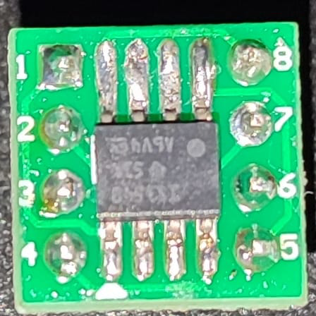
 Design with ISO1540 in Cirkit Designer
Introduction
The ISO1540 is an isolated voltage regulator designed to provide a stable output voltage while electrically isolating the input and output sides. This isolation ensures that noise, surges, or ground loops on one side do not affect the other, making it ideal for applications requiring robust electrical isolation. The ISO1540 is commonly used in industrial automation, medical devices, and communication systems where signal integrity and safety are critical.
Explore Projects Built with ISO1540
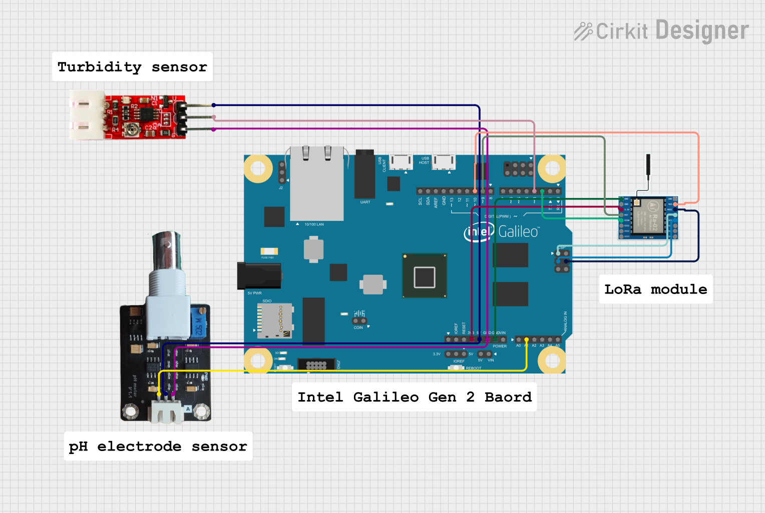 Open Project in Cirkit Designer
 Open Project in Cirkit Designer
 Open Project in Cirkit Designer
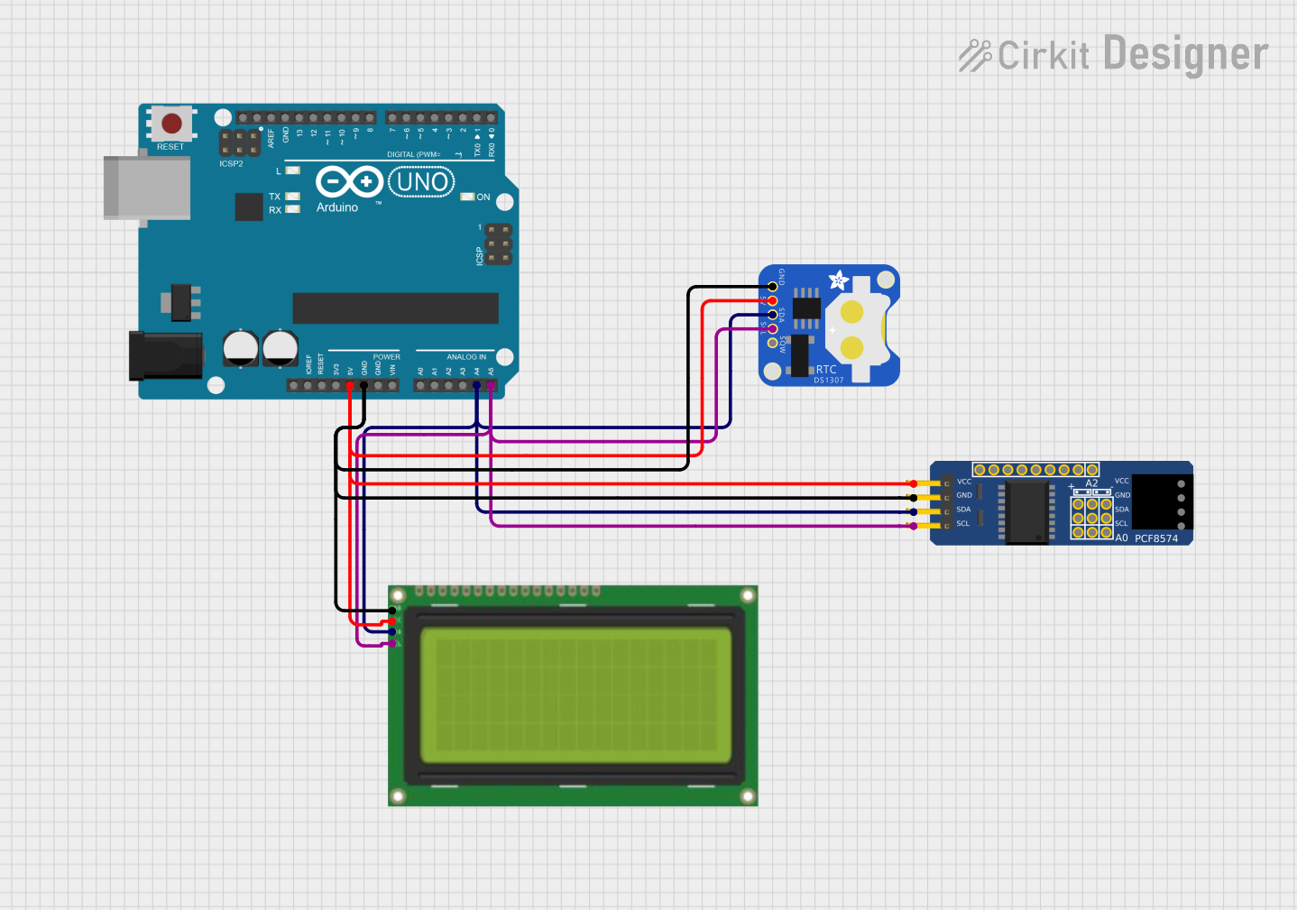 Open Project in Cirkit Designer
Explore Projects Built with ISO1540
Open Project in Cirkit DesignerOpen Project in Cirkit DesignerOpen Project in Cirkit DesignerOpen Project in Cirkit DesignerCommon Applications:
- Industrial control systems
- Medical equipment requiring patient isolation
- Communication systems with noise-sensitive components
- Power supplies for isolated circuits
Technical Specifications
The ISO1540 is designed to meet stringent performance and safety requirements. Below are its key technical specifications:
Key Specifications:
| Parameter | Value |
|---|---|
| Input Voltage Range | 3.0 V to 5.5 V |
| Output Voltage | 3.3 V or 5 V (fixed options) |
| Isolation Voltage | 2500 VRMS |
| Maximum Output Current | 50 mA |
| Operating Temperature | -40°C to +85°C |
| Quiescent Current | 1.5 mA (typical) |
| Package Type | SOIC-8 |
Pin Configuration:
The ISO1540 is available in an 8-pin SOIC package. The pinout and descriptions are as follows:
| Pin Number | Pin Name | Description |
|---|---|---|
| 1 | VCC1 | Input supply voltage for the primary side |
| 2 | GND1 | Ground for the primary side |
| 3 | NC | No connection (leave unconnected) |
| 4 | OUT | Regulated output voltage |
| 5 | GND2 | Ground for the secondary side |
| 6 | NC | No connection (leave unconnected) |
| 7 | VCC2 | Input supply voltage for the secondary side |
| 8 | EN | Enable pin (active high, enables the regulator when pulled high) |
Usage Instructions
To use the ISO1540 in a circuit, follow these steps:
Power Supply Connections:
- Connect the primary side power supply to
VCC1andGND1. - Connect the secondary side power supply to
VCC2andGND2.
- Connect the primary side power supply to
Output Voltage:
- The regulated output voltage is available at the
OUTpin. Ensure the load connected to this pin does not exceed the maximum output current of 50 mA.
- The regulated output voltage is available at the
Enable Pin:
- The
ENpin must be pulled high to enable the regulator. If unused, connect it toVCC1through a pull-up resistor.
- The
Bypass Capacitors:
- Place decoupling capacitors (e.g., 0.1 µF and 10 µF) close to the
VCC1andVCC2pins to ensure stable operation.
- Place decoupling capacitors (e.g., 0.1 µF and 10 µF) close to the
Isolation:
- Ensure that the primary and secondary grounds (
GND1andGND2) are not connected to maintain electrical isolation.
- Ensure that the primary and secondary grounds (
Example Circuit:
Below is an example of how to connect the ISO1540 in a circuit:
Primary Side:                     Secondary Side:
+3.3V (VCC1) --------------------+ +3.3V (VCC2)
                                 |
                                [ISO1540]
                                 |
GND1 ---------------------------+ GND2
Arduino UNO Integration:
The ISO1540 is not directly used for signal processing but can be used to isolate power supplies for Arduino-based projects. For example, it can provide a stable, isolated power supply to sensors or modules connected to the Arduino.
// Example: Using ISO1540 to power an isolated sensor
// Ensure the ISO1540 output is connected to the sensor's VCC and GND pins

void setup() {
  // Initialize serial communication for debugging
  Serial.begin(9600);

  // Ensure the ISO1540 enable pin is set high
  pinMode(8, OUTPUT); // Assuming pin 8 is connected to ISO1540 EN pin
  digitalWrite(8, HIGH); // Enable the ISO1540 regulator
}

void loop() {
  // Your main code here
  Serial.println("ISO1540 is providing isolated power to the sensor.");
  delay(1000);
}
Troubleshooting and FAQs
Common Issues:
No Output Voltage:
- Ensure the
ENpin is pulled high. If left floating, the regulator will remain disabled. - Verify that the input voltage on
VCC1andVCC2is within the specified range.
- Ensure the
Output Voltage Instability:
- Check that decoupling capacitors are placed close to the
VCC1andVCC2pins. - Ensure the load current does not exceed the maximum output current of 50 mA.
- Check that decoupling capacitors are placed close to the
Loss of Isolation:
- Verify that the primary and secondary grounds (
GND1andGND2) are not connected.
- Verify that the primary and secondary grounds (
Overheating:
- Ensure the component is not operating beyond its maximum power dissipation limits.
- Check for proper ventilation or heat sinking if necessary.
FAQs:
Q: Can the ISO1540 be used for signal isolation?
A: No, the ISO1540 is designed for power isolation, not signal isolation. For signal isolation, consider using optocouplers or digital isolators.
Q: What happens if the EN pin is left floating?
A: The regulator will remain disabled. Always pull the EN pin high to enable the device.
Q: Can I use the ISO1540 with a 12V input?
A: No, the input voltage range is limited to 3.0 V to 5.5 V. Exceeding this range may damage the component.
Q: Is the ISO1540 suitable for high-current applications?
A: No, the ISO1540 is designed for low-current applications with a maximum output current of 50 mA.
By following these guidelines and best practices, the ISO1540 can be effectively integrated into your designs to provide reliable and isolated power.