Cirkit Designer Logo
Cirkit Designer
Your all-in-one circuit design IDE
Home / 
Component Documentation

How to Use mini step down buck converter: Examples, Pinouts, and Specs

Image of mini step down buck converter
Cirkit Designer LogoDesign with mini step down buck converter in Cirkit Designer

Introduction

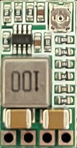
A Mini Step Down Buck Converter is a compact and efficient voltage regulator designed to step down an input voltage to a lower output voltage level. This electronic component is based on the buck converter topology, which uses a combination of inductors, capacitors, and switching elements to reduce the voltage. It is commonly used in battery-operated devices, power supplies, and any application where voltage regulation is required to provide a stable and lower voltage to electronic circuits.

Explore Projects Built with mini step down buck converter

Use Cirkit Designer to design, explore, and prototype these projects online. Some projects support real-time simulation. Click "Open Project" to start designing instantly!
Dual Motor Control Circuit with Directional Switching and Voltage Regulation
Image of Pencuci Kipas: A project utilizing mini step down buck converter in a practical application
This circuit features a 12V battery connected through a rocker switch to two buck converters, one of which steps down the voltage to power two DC mini metal gear motors, and the other is connected to a directional switch that controls a third DC mini metal gear motor. The XL4015 5A DC Buck Step-down converter's output is connected to two motors, allowing them to run at a reduced voltage, while the other buck converter's output is routed through a directional switch to control the direction of the third motor.
Cirkit Designer LogoOpen Project in Cirkit Designer
USB Power Supply with Overcurrent Protection
Image of USB Charging port: A project utilizing mini step down buck converter in a practical application
This circuit is designed to step down voltage from a 12V battery to a lower voltage suitable for USB devices. It includes a buck converter connected to the battery through a fuse and fuse holder for overcurrent protection. The output of the buck converter is connected to a USB female port, providing a regulated power supply for USB-powered devices.
Cirkit Designer LogoOpen Project in Cirkit Designer
Battery-Powered UPS with Step-Down Buck Converter and BMS
Image of Mini ups: A project utilizing mini step down buck converter in a practical application
This circuit is a power management system that steps down a 240V AC input to a lower DC voltage using a buck converter, which then powers a 40W UPS. The UPS is controlled by a rocker switch and is backed up by a battery management system (BMS) connected to three 3.7V batteries in series, ensuring continuous power supply.
Cirkit Designer LogoOpen Project in Cirkit Designer
Battery-Powered ESP32 Devkit V1 with Buck Converter and Switch Control
Image of Autonomus Car: A project utilizing mini step down buck converter in a practical application
This circuit is a power management system that uses two 18650 Li-ion batteries to supply power through a toggle switch and a rocker switch to an LM2956 Buck Converter. The buck converter steps down the voltage to a suitable level for a connected device via a Micro USB cable.
Cirkit Designer LogoOpen Project in Cirkit Designer

Explore Projects Built with mini step down buck converter

Use Cirkit Designer to design, explore, and prototype these projects online. Some projects support real-time simulation. Click "Open Project" to start designing instantly!
Image of Pencuci Kipas: A project utilizing mini step down buck converter in a practical application
Dual Motor Control Circuit with Directional Switching and Voltage Regulation
This circuit features a 12V battery connected through a rocker switch to two buck converters, one of which steps down the voltage to power two DC mini metal gear motors, and the other is connected to a directional switch that controls a third DC mini metal gear motor. The XL4015 5A DC Buck Step-down converter's output is connected to two motors, allowing them to run at a reduced voltage, while the other buck converter's output is routed through a directional switch to control the direction of the third motor.
Cirkit Designer LogoOpen Project in Cirkit Designer
Image of USB Charging port: A project utilizing mini step down buck converter in a practical application
USB Power Supply with Overcurrent Protection
This circuit is designed to step down voltage from a 12V battery to a lower voltage suitable for USB devices. It includes a buck converter connected to the battery through a fuse and fuse holder for overcurrent protection. The output of the buck converter is connected to a USB female port, providing a regulated power supply for USB-powered devices.
Cirkit Designer LogoOpen Project in Cirkit Designer
Image of Mini ups: A project utilizing mini step down buck converter in a practical application
Battery-Powered UPS with Step-Down Buck Converter and BMS
This circuit is a power management system that steps down a 240V AC input to a lower DC voltage using a buck converter, which then powers a 40W UPS. The UPS is controlled by a rocker switch and is backed up by a battery management system (BMS) connected to three 3.7V batteries in series, ensuring continuous power supply.
Cirkit Designer LogoOpen Project in Cirkit Designer
Image of Autonomus Car: A project utilizing mini step down buck converter in a practical application
Battery-Powered ESP32 Devkit V1 with Buck Converter and Switch Control
This circuit is a power management system that uses two 18650 Li-ion batteries to supply power through a toggle switch and a rocker switch to an LM2956 Buck Converter. The buck converter steps down the voltage to a suitable level for a connected device via a Micro USB cable.
Cirkit Designer LogoOpen Project in Cirkit Designer

Common Applications and Use Cases

  • Powering low-voltage devices from higher voltage sources
  • Battery charging circuits for portable devices
  • Providing stable voltage to sensitive electronics like microcontrollers
  • Automotive electronics where the car battery voltage needs to be stepped down
  • LED drivers for controlling the brightness of high-power LEDs

Technical Specifications

Key Technical Details

  • Input Voltage Range: Typically ranges from a few volts above the desired output up to a specified maximum (e.g., 4.5V to 28V)
  • Output Voltage Range: Adjustable or fixed, depending on the model (e.g., 0.8V to 20V)
  • Maximum Output Current: Depends on the model, can range from a few milliamps to several amps (e.g., 3A)
  • Efficiency: Varies with load, but typically around 80-95%
  • Switching Frequency: The frequency at which the internal switch operates, often in the range of hundreds of kHz to MHz
  • Operating Temperature: The safe ambient temperature range for operation (e.g., -40°C to +85°C)

Pin Configuration and Descriptions

Pin Number Name Description
1 VIN Input voltage supply pin. Connect to the source voltage that needs to be stepped down.
2 GND Ground pin. Connect to the system ground.
3 VOUT Output voltage pin. Provides the regulated lower voltage.
4 ADJ Adjustment pin. Used to set the output voltage with an external resistor divider (if adjustable).

Usage Instructions

How to Use the Component in a Circuit

  1. Input Voltage: Connect the source voltage to the VIN pin, ensuring it is within the specified input voltage range.
  2. Ground Connection: Connect the GND pin to the common ground of the circuit.
  3. Output Voltage: Connect the load to the VOUT pin. For adjustable models, set the desired output voltage using a resistor divider connected to the ADJ pin.
  4. Heat Management: If the converter is expected to handle high power, ensure adequate heat sinking or airflow to prevent overheating.

Important Considerations and Best Practices

  • Always verify that the input voltage does not exceed the maximum rating of the buck converter.
  • Use capacitors at the input and output for filtering and to improve transient response.
  • Keep the leads short and the layout compact to minimize noise and electromagnetic interference.
  • Avoid placing high-frequency switching components near sensitive analog circuitry to prevent noise coupling.

Troubleshooting and FAQs

Common Issues Users Might Face

  • Output Voltage is Too High or Low: Check the ADJ pin resistor divider values and connections.
  • Converter is Overheating: Ensure the input voltage is within the specified range and that the load does not exceed the maximum current rating.
  • Noise in the Circuit: Verify the layout is compact and that adequate filtering is in place.

Solutions and Tips for Troubleshooting

  • Incorrect Output Voltage: Recalculate and adjust the resistor values for the ADJ pin if necessary.
  • Thermal Issues: Improve heat dissipation with a heat sink or by improving airflow around the converter.
  • Noise Issues: Use shielded cables for connections and place filtering capacitors close to the input and output pins.

Example Code for Arduino UNO

// Example code to read the output voltage of the buck converter using Arduino UNO

const int analogPin = A0; // Connect the VOUT of the buck converter to A0
float vOut = 0.0;        // Variable to store the output voltage

void setup() {
  Serial.begin(9600);    // Start serial communication at 9600 baud
}

void loop() {
  int sensorValue = analogRead(analogPin); // Read the analog value from A0
  vOut = sensorValue * (5.0 / 1023.0);    // Convert to voltage

  Serial.print("Output Voltage: ");
  Serial.print(vOut);
  Serial.println(" V");

  delay(1000); // Wait for 1 second before reading again
}

Note: The code assumes that the Arduino's reference voltage is 5V and that the buck converter's output voltage does not exceed this value. If the output voltage can be higher, a voltage divider or a different reference voltage should be used to prevent damage to the Arduino.

Remember to adjust the code comments and line lengths as per the 80-character limit for readability and maintainability.