How to Use rj10 Female pass through adapter breakout: Examples, Pinouts, and Specs
Introduction
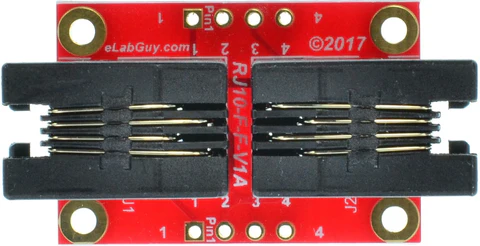
The RJ10 Female Pass-Through Adapter Breakout is a versatile component designed to simplify the connection and wiring of RJ10 female connectors. This breakout adapter provides easy access to individual pins of the RJ10 connector, making it ideal for prototyping, testing, and integrating RJ10-based devices into custom circuits. Its compact design and straightforward pinout make it a valuable tool for hobbyists, engineers, and technicians.
Explore Projects Built with rj10 Female pass through adapter breakout


Explore Projects Built with rj10 Female pass through adapter breakout
Common Applications and Use Cases
- Connecting RJ10-based devices (e.g., telephone handsets, headsets) to custom circuits.
- Prototyping and testing RJ10-compatible hardware.
- Debugging and troubleshooting RJ10 connections.
- Educational projects involving telecommunication hardware.
Technical Specifications
The RJ10 Female Pass-Through Adapter Breakout is designed to provide a simple and reliable interface for RJ10 connectors. Below are its key technical details:
Key Specifications
- Connector Type: RJ10 (4P4C, 4-position, 4-conductor)
- Breakout Pins: 4 pins corresponding to the RJ10 connector's conductors.
- Voltage Rating: Up to 50V DC (dependent on connected circuit).
- Current Rating: Up to 1A per pin.
- PCB Dimensions: Typically 25mm x 20mm (may vary by manufacturer).
- Mounting Options: Through-hole or adhesive mounting.
Pin Configuration and Descriptions
The RJ10 breakout adapter maps the 4 conductors of the RJ10 connector to individual pins on the breakout board. The pinout is as follows:
| Pin Number | RJ10 Signal | Description |
|---|---|---|
| 1 | Tip | Audio signal or data line 1 |
| 2 | Ring | Audio signal or data line 2 |
| 3 | Ring | Audio signal or data line 3 |
| 4 | Tip | Audio signal or data line 4 |
Note: The exact signal mapping depends on the device connected to the RJ10 port. Always refer to the device's documentation for proper wiring.
Usage Instructions
How to Use the Component in a Circuit
Prepare the Breakout Adapter:
- Ensure the breakout adapter is securely mounted on a breadboard or PCB.
- Verify that the RJ10 connector is clean and free of debris.
Connect the RJ10 Device:
- Plug the RJ10 cable into the female connector on the breakout adapter.
- Ensure a snug and secure connection.
Wire the Breakout Pins:
- Use jumper wires to connect the breakout pins to your circuit.
- Refer to the pin configuration table above to match the correct signals.
Power and Test:
- Power your circuit and test the functionality of the connected RJ10 device.
- Use a multimeter to verify continuity and signal integrity if needed.
Important Considerations and Best Practices
- Signal Compatibility: Ensure the connected RJ10 device is compatible with your circuit's voltage and current levels.
- Avoid Overloading: Do not exceed the breakout adapter's voltage and current ratings.
- Secure Connections: Use proper strain relief for the RJ10 cable to prevent accidental disconnections.
- Polarity Check: Double-check the polarity of signals before powering the circuit to avoid damage.
Example: Connecting to an Arduino UNO
The RJ10 breakout adapter can be used to interface RJ10 devices with an Arduino UNO. Below is an example of reading a signal from an RJ10 device:
// Example: Reading a signal from an RJ10 device connected to pin A0
// Ensure the RJ10 breakout adapter is properly wired to the Arduino UNO.

const int rj10SignalPin = A0; // Analog pin connected to RJ10 breakout
int signalValue = 0;          // Variable to store the signal value

void setup() {
  Serial.begin(9600); // Initialize serial communication
  pinMode(rj10SignalPin, INPUT); // Set the RJ10 pin as input
}

void loop() {
  signalValue = analogRead(rj10SignalPin); // Read the signal value
  Serial.print("Signal Value: ");
  Serial.println(signalValue); // Print the signal value to the Serial Monitor
  delay(500); // Wait for 500ms before the next reading
}
Note: The above code assumes the RJ10 device outputs an analog signal. Modify the code as needed for digital signals or other use cases.
Troubleshooting and FAQs
Common Issues and Solutions
No Signal Detected:
- Cause: Loose or incorrect wiring.
- Solution: Verify all connections and ensure the RJ10 cable is securely plugged in.
Intermittent Signal:
- Cause: Poor contact in the RJ10 connector.
- Solution: Clean the connector and ensure proper strain relief for the cable.
Overheating:
- Cause: Exceeding the voltage or current rating.
- Solution: Check the circuit's power requirements and ensure they are within the adapter's specifications.
Incorrect Signal Mapping:
- Cause: Misinterpreted pinout.
- Solution: Double-check the pin configuration table and the connected device's documentation.
FAQs
Q: Can this breakout adapter be used with RJ11 or RJ12 connectors?
A: No, the RJ10 breakout adapter is specifically designed for RJ10 connectors (4P4C). RJ11 and RJ12 connectors have different pin configurations and sizes.
Q: Is the breakout adapter compatible with digital signals?
A: Yes, the breakout adapter can handle both analog and digital signals, provided they are within the voltage and current ratings.
Q: Can I use this adapter for audio applications?
A: Yes, the RJ10 breakout adapter is commonly used for audio signals, such as those from telephone handsets or headsets.
Q: How do I identify the pinout of my RJ10 device?
A: Refer to the device's datasheet or documentation for the correct pinout. Use a multimeter to verify signal continuity if needed.