
How to Use PIC-ICSP: Examples, Pinouts, and Specs
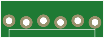
 Design with PIC-ICSP in Cirkit Designer
Introduction
The PIC-ICSP (In-Circuit Serial Programming) is a programming interface designed for Microchip's PIC microcontrollers. It allows users to upload firmware directly to the microcontroller without needing to remove it from the circuit. This feature is particularly useful for development, debugging, and production environments, as it simplifies the programming process and reduces the need for external programming hardware.
Explore Projects Built with PIC-ICSP
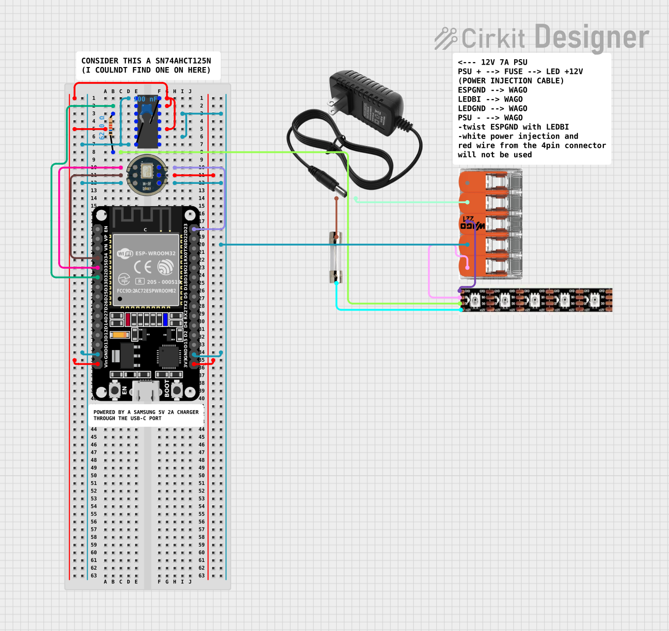 Open Project in Cirkit Designer
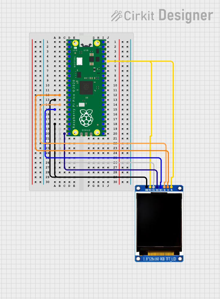 Open Project in Cirkit Designer
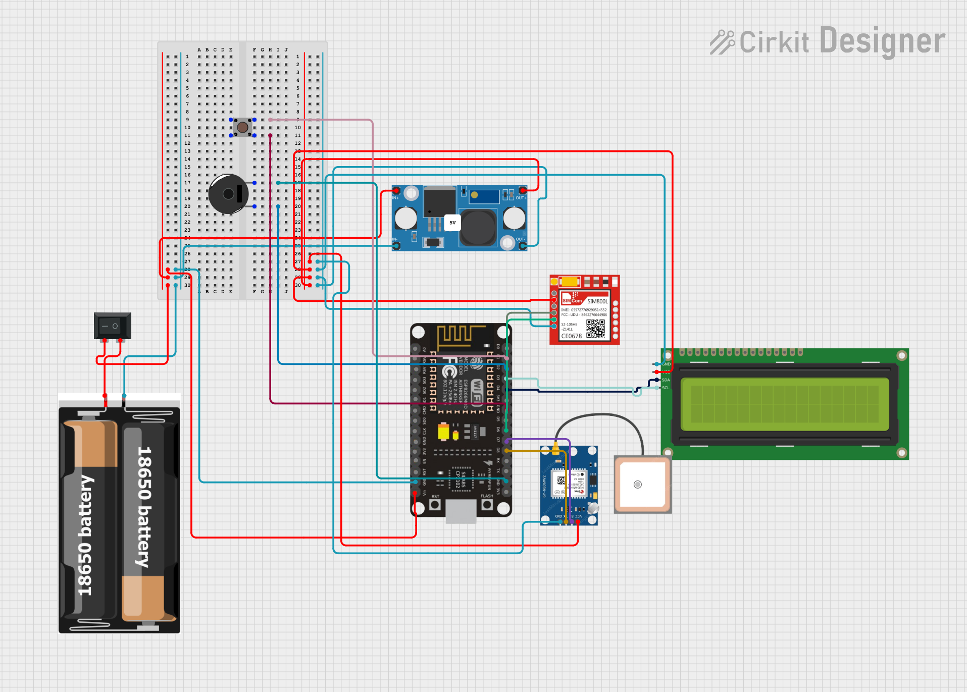 Open Project in Cirkit Designer
 Open Project in Cirkit Designer
Explore Projects Built with PIC-ICSP
Open Project in Cirkit DesignerOpen Project in Cirkit DesignerOpen Project in Cirkit DesignerOpen Project in Cirkit DesignerCommon Applications and Use Cases
- Firmware development and debugging for PIC microcontrollers
- Programming PIC microcontrollers in embedded systems
- Updating firmware in production environments
- Prototyping and testing circuits with PIC microcontrollers
Technical Specifications
Key Technical Details
- Programming Protocol: Serial communication
- Voltage Levels: Typically 3.3V or 5V (depending on the PIC microcontroller)
- Programming Pins: VPP/MCLR, VDD, VSS, PGD (Data), PGC (Clock)
- Connector Type: 6-pin header (commonly used)
- Supported Microcontrollers: Most PIC microcontrollers with ICSP capability
Pin Configuration and Descriptions
The PIC-ICSP interface typically uses a 6-pin header. Below is the pinout and description:
| Pin | Name | Description |
|---|---|---|
| 1 | VPP/MCLR | Programming voltage input (used to reset and enter programming mode) |
| 2 | VDD | Positive supply voltage for the microcontroller |
| 3 | VSS | Ground connection |
| 4 | PGD (ICSPDAT) | Data line for serial communication between the programmer and microcontroller |
| 5 | PGC (ICSPCLK) | Clock line for synchronizing data transfer |
| 6 | AUX (Optional) | Optional pin for additional functionality (varies by programmer) |
Note: The pin order may vary depending on the programmer or development board. Always refer to the specific programmer's documentation for exact pinout details.
Usage Instructions
How to Use the PIC-ICSP in a Circuit
Connect the ICSP Header:
- Ensure the 6-pin ICSP header is correctly connected to the corresponding pins on the PIC microcontroller.
- Double-check the pinout to avoid incorrect connections, which could damage the microcontroller or programmer.
Power the Circuit:
- Provide the appropriate supply voltage (VDD) to the microcontroller. Most PIC microcontrollers operate at 3.3V or 5V.
- Ensure the circuit's ground (VSS) is shared with the programmer.
Enter Programming Mode:
- The programmer will assert the VPP/MCLR pin to a high voltage (typically 12V) to place the microcontroller into programming mode.
Upload Firmware:
- Use compatible software (e.g., MPLAB X IDE) to upload the firmware to the microcontroller via the ICSP interface.
- Select the correct microcontroller model and programmer in the software settings.
Verify the Firmware:
- After programming, verify the firmware to ensure it was uploaded correctly. Most programming tools include a verification step.
Important Considerations and Best Practices
- Check Compatibility: Ensure the programmer supports the specific PIC microcontroller you are using.
- Avoid Noise: Keep the ICSP lines (PGD and PGC) short and free from electrical noise to ensure reliable communication.
- Protect the Circuit: If the microcontroller is part of a larger circuit, isolate sensitive components during programming to prevent damage.
- Use Pull-Up Resistors: Some PIC microcontrollers may require pull-up resistors on the MCLR pin for proper operation.
Example: Using PIC-ICSP with MPLAB X IDE
Below is an example of how to configure and program a PIC microcontroller using MPLAB X IDE:
- Open MPLAB X IDE and create a new project.
- Select the target PIC microcontroller and the ICSP-compatible programmer (e.g., PICkit 4).
- Connect the programmer to the ICSP header on your circuit.
- Write or import your firmware code.
- Click "Make and Program Device" to compile and upload the firmware.
Troubleshooting and FAQs
Common Issues and Solutions
The programmer cannot detect the microcontroller.
- Solution: Check all connections, especially the ICSP header. Ensure the VDD and VSS pins are properly connected and the microcontroller is powered.
Programming fails or is unreliable.
- Solution: Verify that the ICSP lines (PGD and PGC) are not too long or affected by electrical noise. Use shorter wires and shield them if necessary.
The microcontroller does not enter programming mode.
- Solution: Ensure the VPP/MCLR pin is receiving the correct programming voltage (typically 12V). Check the programmer's settings.
Firmware verification fails after programming.
- Solution: Ensure the firmware file is compatible with the target microcontroller. Recheck the connections and try programming again.
FAQs
Can I use the PIC-ICSP interface for debugging?
- Yes, many PIC microcontrollers support debugging via the ICSP interface when used with compatible tools like MPLAB X IDE.
What happens if I connect the ICSP pins incorrectly?
- Incorrect connections can damage the microcontroller or programmer. Always double-check the pinout before powering the circuit.
Do I need external components for ICSP programming?
- In most cases, no additional components are required. However, some circuits may benefit from pull-up resistors or decoupling capacitors for stability.
Can I program a PIC microcontroller while it is in a circuit?
- Yes, as long as the circuit does not interfere with the ICSP lines and the microcontroller is powered correctly.
By following this documentation, you can effectively use the PIC-ICSP interface to program and debug PIC microcontrollers in a variety of applications.