How to Use 6 IR Array: Examples, Pinouts, and Specs
Introduction
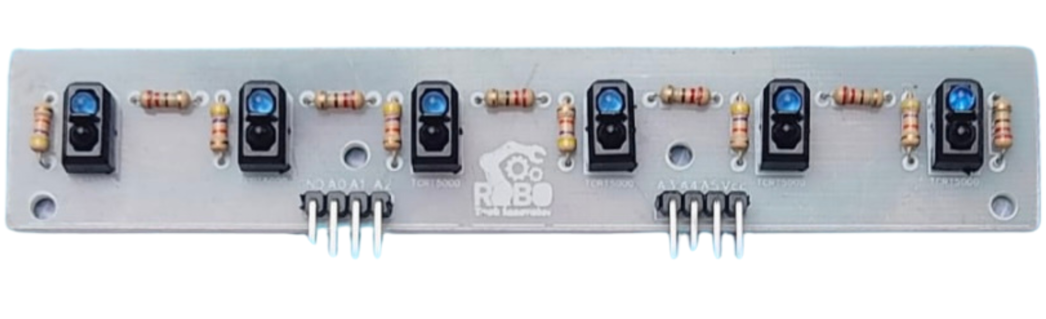
The 6 IR Array (Manufacturer: RoboKart, Part ID: TCRT5000) is a compact module consisting of six infrared sensors arranged in a linear configuration. Each sensor in the array uses the TCRT5000 IR sensor, which combines an infrared emitter and a phototransistor to detect reflected IR light. This module is commonly used for applications such as line-following robots, obstacle detection, edge detection, and object tracking.
Explore Projects Built with 6 IR Array
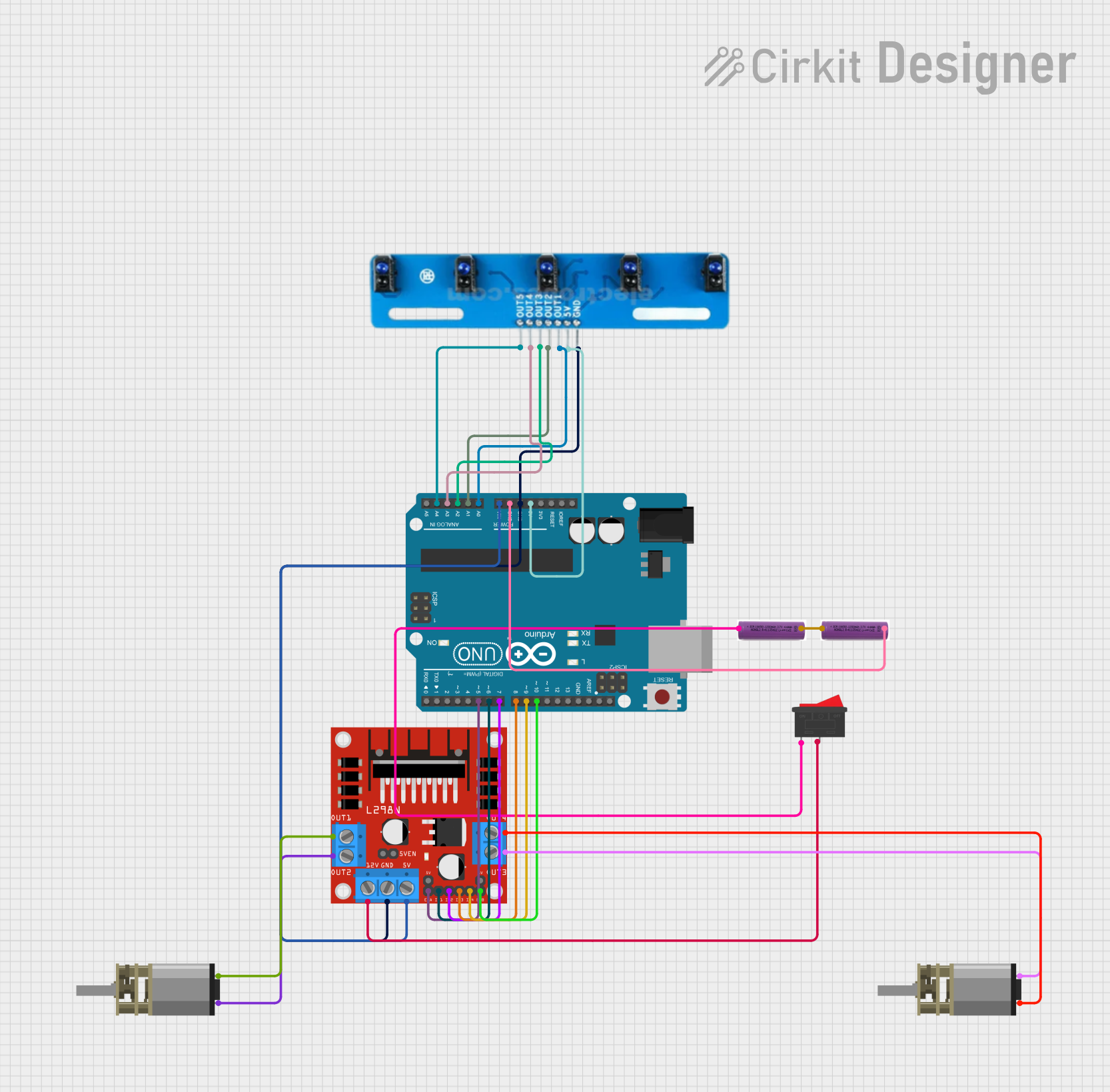
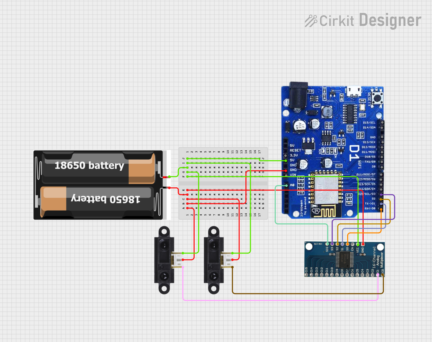
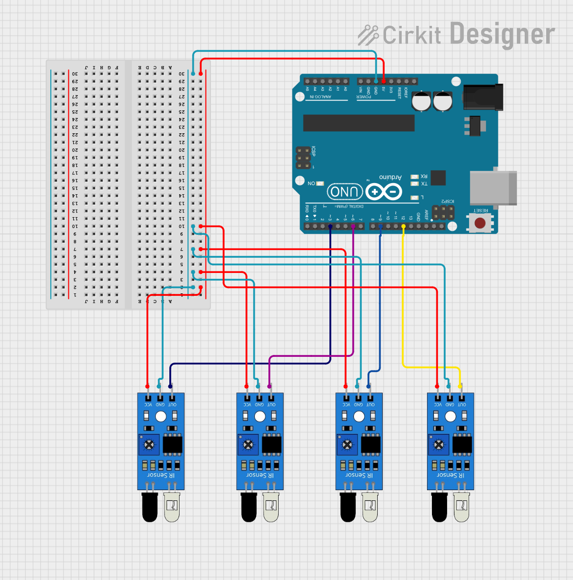
Explore Projects Built with 6 IR Array
Common Applications
- Line-following robots: Detecting black or white lines on a surface.
- Obstacle detection: Identifying objects in close proximity.
- Edge detection: Preventing robots from falling off edges.
- Object tracking: Following moving objects or detecting their position.
Technical Specifications
The following table outlines the key technical details of the 6 IR Array:
| Parameter | Value |
|---|---|
| Operating Voltage | 3.3V to 5V |
| Operating Current | ~60mA (varies with usage) |
| Detection Range | 2mm to 15mm (adjustable) |
| Output Type | Digital (High/Low) |
| Sensor Type | TCRT5000 (IR emitter + receiver) |
| Dimensions | ~70mm x 15mm x 10mm |
| Weight | ~15g |
Pin Configuration and Descriptions
The 6 IR Array has a set of pins for power, ground, and individual sensor outputs. The pin configuration is as follows:
| Pin Name | Description |
|---|---|
| VCC | Power supply input (3.3V to 5V). |
| GND | Ground connection. |
| OUT1 | Digital output from Sensor 1 (High = no object detected, Low = object detected). |
| OUT2 | Digital output from Sensor 2. |
| OUT3 | Digital output from Sensor 3. |
| OUT4 | Digital output from Sensor 4. |
| OUT5 | Digital output from Sensor 5. |
| OUT6 | Digital output from Sensor 6. |
Usage Instructions
How to Use the 6 IR Array in a Circuit
- Power the Module: Connect the
VCCpin to a 3.3V or 5V power source and theGNDpin to ground. - Connect Outputs: Connect the
OUT1toOUT6pins to the digital input pins of a microcontroller (e.g., Arduino UNO). - Adjust Sensitivity: Use the onboard potentiometers to adjust the sensitivity of each sensor. Turn clockwise to increase sensitivity and counterclockwise to decrease it.
- Place the Array: Position the array close to the surface or object to be detected (2mm to 15mm range).
Important Considerations
- Ambient Light: The module may be affected by strong ambient light. Use it in controlled lighting conditions for best results.
- Surface Reflectivity: The detection range and accuracy depend on the reflectivity of the surface. Darker surfaces reflect less IR light, while lighter surfaces reflect more.
- Power Supply: Ensure a stable power supply to avoid erratic sensor behavior.
Example Code for Arduino UNO
Below is an example code snippet to read data from the 6 IR Array using an Arduino UNO:
// Define the pins connected to the 6 IR Array outputs
#define SENSOR1_PIN 2
#define SENSOR2_PIN 3
#define SENSOR3_PIN 4
#define SENSOR4_PIN 5
#define SENSOR5_PIN 6
#define SENSOR6_PIN 7

void setup() {
  // Initialize serial communication for debugging
  Serial.begin(9600);

  // Set sensor pins as inputs
  pinMode(SENSOR1_PIN, INPUT);
  pinMode(SENSOR2_PIN, INPUT);
  pinMode(SENSOR3_PIN, INPUT);
  pinMode(SENSOR4_PIN, INPUT);
  pinMode(SENSOR5_PIN, INPUT);
  pinMode(SENSOR6_PIN, INPUT);
}

void loop() {
  // Read the state of each sensor
  int sensor1 = digitalRead(SENSOR1_PIN);
  int sensor2 = digitalRead(SENSOR2_PIN);
  int sensor3 = digitalRead(SENSOR3_PIN);
  int sensor4 = digitalRead(SENSOR4_PIN);
  int sensor5 = digitalRead(SENSOR5_PIN);
  int sensor6 = digitalRead(SENSOR6_PIN);

  // Print sensor states to the Serial Monitor
  Serial.print("Sensor 1: "); Serial.print(sensor1);
  Serial.print(" | Sensor 2: "); Serial.print(sensor2);
  Serial.print(" | Sensor 3: "); Serial.print(sensor3);
  Serial.print(" | Sensor 4: "); Serial.print(sensor4);
  Serial.print(" | Sensor 5: "); Serial.print(sensor5);
  Serial.print(" | Sensor 6: "); Serial.println(sensor6);

  // Add a small delay for readability
  delay(100);
}
Notes:
- The
digitalRead()function returnsHIGHwhen no object is detected andLOWwhen an object is detected. - Adjust the sensitivity of each sensor using the onboard potentiometers for optimal performance.
Troubleshooting and FAQs
Common Issues
No Output from Sensors:
- Cause: Incorrect wiring or insufficient power supply.
- Solution: Double-check the connections and ensure the power supply is stable and within the specified range.
Erratic Sensor Behavior:
- Cause: Ambient light interference or unstable power.
- Solution: Use the module in a controlled lighting environment and ensure a stable power source.
Inconsistent Detection:
- Cause: Improper sensitivity settings or surface reflectivity issues.
- Solution: Adjust the potentiometers to fine-tune sensitivity and test on different surfaces.
FAQs
Q1: Can the 6 IR Array detect transparent objects?
A1: No, the module is not designed to detect transparent objects as they do not reflect sufficient IR light.
Q2: What is the maximum detection range?
A2: The detection range is adjustable between 2mm and 15mm, depending on the surface reflectivity and sensitivity settings.
Q3: Can I use this module with a 3.3V microcontroller?
A3: Yes, the module is compatible with both 3.3V and 5V systems.
Q4: How do I know if a sensor is working?
A4: Each sensor has an onboard LED that lights up when it detects an object. You can also verify functionality by reading the digital output.
By following this documentation, you can effectively integrate and troubleshoot the 6 IR Array in your projects.