How to Use TTL To USB Converter: Examples, Pinouts, and Specs
Introduction
The TTL to USB Converter (Manufacturer: CSD, Part ID: VVSD) is a versatile device designed to bridge communication between TTL (Transistor-Transistor Logic) devices and USB-enabled systems. It converts TTL-level signals to USB signals, enabling seamless data transfer and communication. This component is widely used in embedded systems, microcontroller programming, and serial communication applications.
Explore Projects Built with TTL To USB Converter


Explore Projects Built with TTL To USB Converter
Common Applications and Use Cases
- Programming and debugging microcontrollers (e.g., Arduino, ESP32, STM32)
- Interfacing TTL-based sensors or modules with a computer
- Serial communication between embedded devices and PCs
- USB-to-serial adapters for legacy systems
- Data logging and monitoring applications
Technical Specifications
The following table outlines the key technical details of the CSD VVSD TTL to USB Converter:
| Parameter | Specification |
|---|---|
| Input Voltage (TTL) | 3.3V or 5V (selectable) |
| USB Standard | USB 2.0 (compatible with USB 1.1) |
| Baud Rate | 300 bps to 3 Mbps |
| Operating Temperature | -40°C to +85°C |
| Connector Type | USB Type-A or Micro-USB (varies by model) |
| Chipset | FT232RL or CH340 (varies by version) |
| Dimensions | 40mm x 15mm x 5mm |
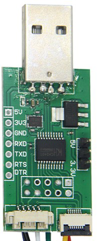
Pin Configuration and Descriptions
The TTL to USB Converter typically has the following pin configuration:
| Pin Name | Description |
|---|---|
| GND | Ground connection |
| VCC | Power input (3.3V or 5V, depending on the device's operating voltage) |
| TXD | Transmit data pin (TTL output, connects to RXD of the target device) |
| RXD | Receive data pin (TTL input, connects to TXD of the target device) |
| DTR | Data Terminal Ready (used for resetting microcontrollers like Arduino) |
| CTS | Clear to Send (optional, used for hardware flow control in some applications) |
Usage Instructions
How to Use the Component in a Circuit
- Power the Converter: Connect the VCC pin to a 3.3V or 5V power source, depending on the operating voltage of your TTL device. Connect the GND pin to the ground of your circuit.
- Connect TXD and RXD:
- Connect the TXD pin of the converter to the RXD pin of your TTL device.
- Connect the RXD pin of the converter to the TXD pin of your TTL device.
- Optional Connections: If required, connect the DTR pin to the reset pin of your microcontroller for automatic reset during programming.
- Connect to USB: Plug the USB connector into your computer or USB host device.
- Install Drivers: Install the appropriate drivers for the chipset (e.g., FT232RL or CH340) on your computer. These drivers are typically available on the manufacturer's website.
- Test Communication: Use a terminal program (e.g., PuTTY, Tera Term) to test serial communication between the TTL device and your computer.
Important Considerations and Best Practices
- Voltage Compatibility: Ensure the operating voltage of the TTL device matches the VCC voltage of the converter (3.3V or 5V).
- Driver Installation: Verify that the correct drivers are installed for the specific chipset used in your converter.
- Signal Integrity: Use short, high-quality wires to minimize noise and signal degradation.
- Avoid Reverse Connections: Double-check the TXD and RXD connections to prevent communication errors.
- Arduino Example: When using the converter with an Arduino UNO, connect the RXD pin of the converter to the TX pin of the Arduino and the TXD pin of the converter to the RX pin of the Arduino.
Example Code for Arduino UNO
Below is an example of how to use the TTL to USB Converter to send data from an Arduino UNO to a computer:
// Example: Sending data from Arduino UNO to a computer via TTL to USB Converter

void setup() {
  Serial.begin(9600); // Initialize serial communication at 9600 baud
  delay(1000); // Wait for the serial connection to stabilize
  Serial.println("TTL to USB Converter Test");
  // Send a test message to the computer
}

void loop() {
  Serial.println("Hello, World!");
  // Send "Hello, World!" to the computer every second
  delay(1000);
  // Wait for 1 second before sending the next message
}
Troubleshooting and FAQs
Common Issues and Solutions
No Communication Detected:
- Cause: Incorrect TXD/RXD connections.
- Solution: Verify that TXD of the converter is connected to RXD of the TTL device, and vice versa.
Driver Not Recognized:
- Cause: Missing or incorrect driver installation.
- Solution: Download and install the correct driver for the chipset (e.g., FT232RL or CH340) from the manufacturer's website.
Data Corruption or Noise:
- Cause: Long or poor-quality wires causing signal degradation.
- Solution: Use short, shielded wires and ensure proper grounding.
Device Not Resetting (Arduino):
- Cause: DTR pin not connected to the reset pin of the Arduino.
- Solution: Connect the DTR pin of the converter to the reset pin of the Arduino via a 0.1µF capacitor.
FAQs
Q1: Can I use this converter with a 1.8V TTL device?
A1: No, this converter supports 3.3V and 5V TTL levels only. Use a level shifter for 1.8V devices.
Q2: Is this converter compatible with Linux and macOS?
A2: Yes, the converter is compatible with Linux and macOS, but you may need to install the appropriate drivers.
Q3: Can I use this converter for bidirectional communication?
A3: Yes, the TXD and RXD pins support bidirectional communication when properly connected.
Q4: How do I check if the converter is working?
A4: Use a terminal program to send and receive data. You can also perform a loopback test by connecting TXD to RXD and verifying data transmission.
This documentation provides a comprehensive guide to using the CSD VVSD TTL to USB Converter effectively. For further assistance, refer to the manufacturer's support resources.