How to Use AMT103: Examples, Pinouts, and Specs
AMT103 Magnetic Encoder Documentation
1. Introduction
The AMT103 is a non-contact magnetic encoder designed to provide precise angular position feedback. It operates using a Hall effect sensor to detect the position of a rotating magnet, ensuring high accuracy and reliability. This encoder is widely used in motion control systems due to its robust design, compact size, and ability to operate in harsh environments.
Common Applications:
- Robotics: For precise motor control and position feedback.
- Industrial Automation: Used in conveyor systems, CNC machines, and other automated equipment.
- Aerospace: For monitoring and controlling actuators.
- Medical Devices: In applications requiring precise motion control, such as robotic surgery systems.
- Electric Vehicles: For motor position sensing in drivetrain systems.
2. Technical Specifications
The following table outlines the key technical details of the AMT103 encoder:
| Parameter | Value |
|---|---|
| Operating Voltage | 3.3V to 5.5V |
| Current Consumption | 6mA (typical) |
| Resolution | Configurable: 48 to 2048 PPR |
| Output Signal | Quadrature (A/B) |
| Maximum Rotational Speed | 60,000 RPM |
| Operating Temperature | -40°C to +125°C |
| Communication Interface | Digital (TTL-compatible) |
| Mounting Options | Multiple mounting hole patterns |
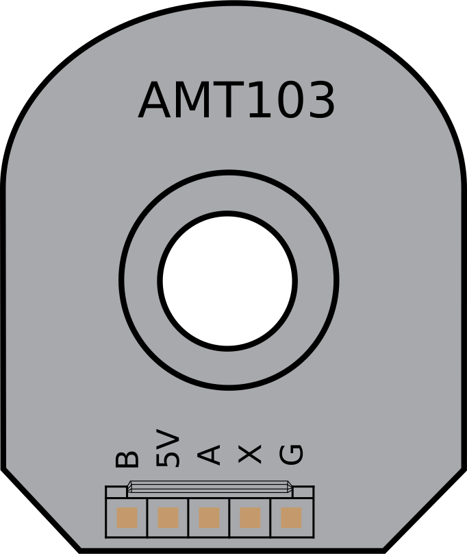
Pin Configuration and Descriptions
The AMT103 encoder has a 5-pin interface. The pinout is as follows:
| Pin | Name | Description |
|---|---|---|
| 1 | VCC | Power supply input (3.3V to 5.5V). |
| 2 | GND | Ground connection. |
| 3 | A | Quadrature output channel A. |
| 4 | B | Quadrature output channel B. |
| 5 | Index | Index pulse output (1 pulse per revolution, optional use). |
3. Usage Instructions
Connecting the AMT103 to a Circuit
To use the AMT103 encoder, follow these steps:
- Power Supply: Connect the
VCCpin to a 3.3V or 5V power source and theGNDpin to ground. - Signal Outputs: Connect the
AandBpins to the input pins of a microcontroller or motor driver to read the quadrature signals. - Index Pulse (Optional): If required, connect the
Indexpin to a microcontroller input to detect the index pulse.
Example Circuit
Below is an example of how to connect the AMT103 to an Arduino UNO:
| AMT103 Pin | Arduino UNO Pin |
|---|---|
| VCC | 5V |
| GND | GND |
| A | Pin 2 (Interrupt) |
| B | Pin 3 (Interrupt) |
| Index | Pin 4 (Optional) |
Important Considerations:
- Ensure the encoder is mounted securely to avoid misalignment during operation.
- Use pull-up resistors on the signal lines if the microcontroller requires them.
- Avoid placing the encoder near strong magnetic fields, as they may interfere with the Hall effect sensor.
4. Example Code for Arduino UNO
The following Arduino code demonstrates how to read the quadrature signals from the AMT103 encoder and calculate the position:
// AMT103 Encoder Example Code for Arduino UNO
// This code reads the quadrature signals (A and B) and calculates the position.

#define ENCODER_PIN_A 2  // Connect AMT103 A pin to Arduino pin 2
#define ENCODER_PIN_B 3  // Connect AMT103 B pin to Arduino pin 3

volatile int encoderPosition = 0;  // Variable to store the encoder position
volatile int lastEncoded = 0;     // Variable to store the last encoder state

void setup() {
  pinMode(ENCODER_PIN_A, INPUT);  // Set pin A as input
  pinMode(ENCODER_PIN_B, INPUT);  // Set pin B as input

  // Enable pull-up resistors
  digitalWrite(ENCODER_PIN_A, HIGH);
  digitalWrite(ENCODER_PIN_B, HIGH);

  // Attach interrupts to the encoder pins
  attachInterrupt(digitalPinToInterrupt(ENCODER_PIN_A), updateEncoder, CHANGE);
  attachInterrupt(digitalPinToInterrupt(ENCODER_PIN_B), updateEncoder, CHANGE);

  Serial.begin(9600);  // Initialize serial communication
}

void loop() {
  // Print the encoder position to the serial monitor
  Serial.print("Encoder Position: ");
  Serial.println(encoderPosition);
  delay(100);  // Delay for readability
}

void updateEncoder() {
  // Read the current state of the encoder pins
  int MSB = digitalRead(ENCODER_PIN_A);  // Most significant bit
  int LSB = digitalRead(ENCODER_PIN_B);  // Least significant bit

  int encoded = (MSB << 1) | LSB;  // Combine the two bits into a single value
  int sum = (lastEncoded << 2) | encoded;  // Combine with the previous state

  // Determine the direction of rotation
  if (sum == 0b1101 || sum == 0b0100 || sum == 0b0010 || sum == 0b1011) {
    encoderPosition++;  // Clockwise rotation
  } else if (sum == 0b1110 || sum == 0b0111 || sum == 0b0001 || sum == 0b1000) {
    encoderPosition--;  // Counterclockwise rotation
  }

  lastEncoded = encoded;  // Update the last state
}
Code Explanation:
- The
updateEncoderfunction is triggered whenever there is a change in the state of the encoder pins. - The quadrature signals are read, and the direction of rotation is determined based on the state transitions.
- The
encoderPositionvariable is updated to reflect the current position of the encoder.
5. Troubleshooting and FAQs
Common Issues and Solutions
| Issue | Possible Cause | Solution |
|---|---|---|
| No output from the encoder | Incorrect wiring or power supply issue | Verify all connections and ensure the encoder is powered correctly. |
| Erratic position readings | Electrical noise or poor grounding | Use shielded cables and ensure proper grounding. |
| Incorrect position or direction | Misaligned encoder or reversed connections | Check the encoder alignment and verify the A/B pin connections. |
| Index pulse not detected | Index pin not connected or misconfigured | Ensure the Index pin is connected and properly configured in the code. |
Frequently Asked Questions (FAQs)
Can the AMT103 operate at 3.3V?
- Yes, the AMT103 supports an operating voltage range of 3.3V to 5.5V.
What is the maximum resolution of the AMT103?
- The AMT103 supports resolutions up to 2048 pulses per revolution (PPR).
How do I configure the resolution?
- The resolution can be configured using the encoder's onboard DIP switches or software, depending on the model.
Can the AMT103 be used in outdoor environments?
- Yes, the AMT103 is designed to operate in harsh environments, with an operating temperature range of -40°C to +125°C.
This documentation provides a comprehensive guide to using the AMT103 magnetic encoder. For further assistance, refer to the manufacturer's datasheet or contact technical support.
Explore Projects Built with AMT103
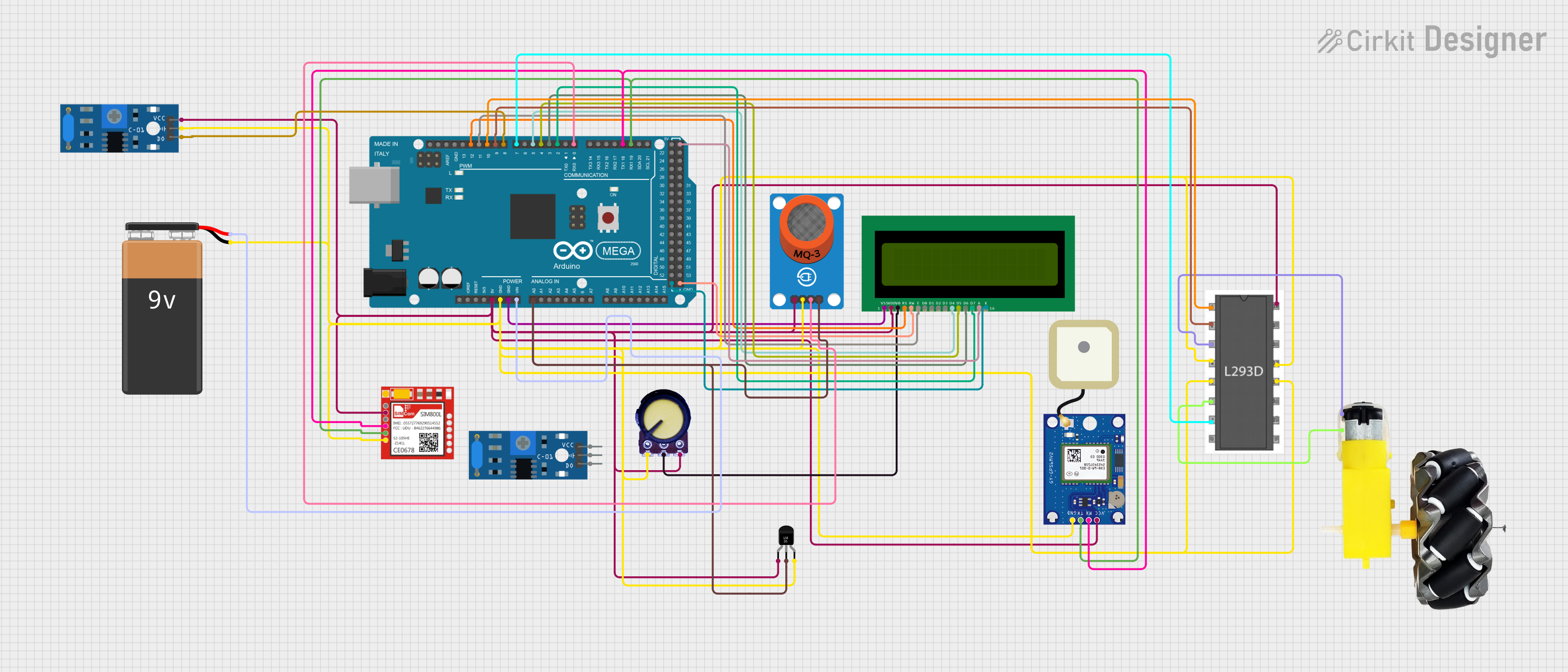

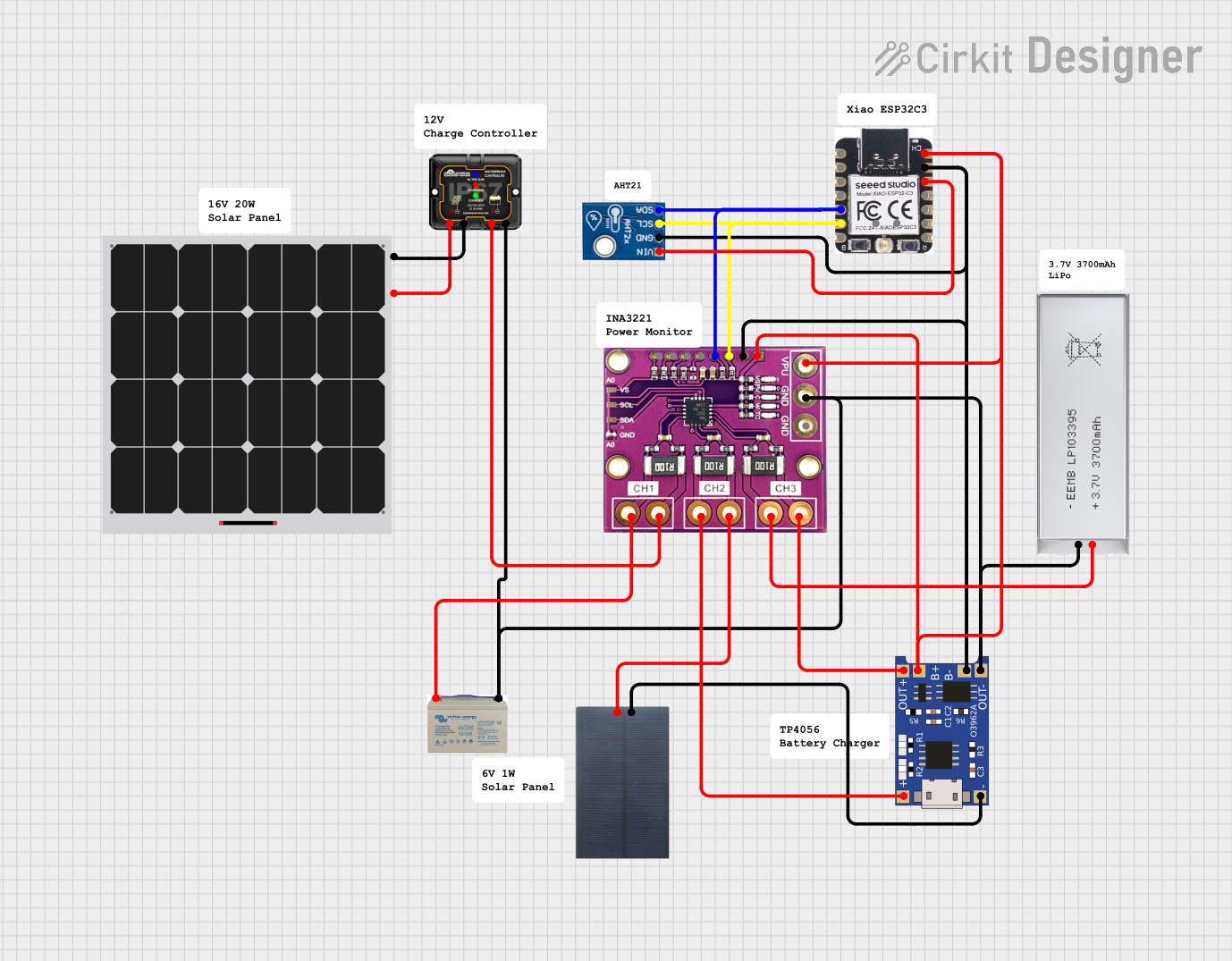

Explore Projects Built with AMT103