How to Use bw16: Examples, Pinouts, and Specs
Introduction
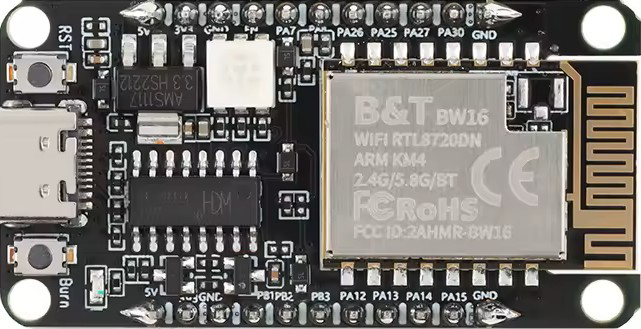
The BW16 is a 16-bit bidirectional bus transceiver designed for efficient data transfer between two devices. It allows communication in both directions, making it ideal for interfacing between systems with differing voltage levels or for general-purpose data bus applications. The BW16 is commonly used in microcontroller-based systems, memory interfacing, and other digital communication setups.
Explore Projects Built with bw16
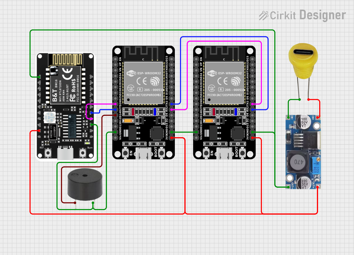
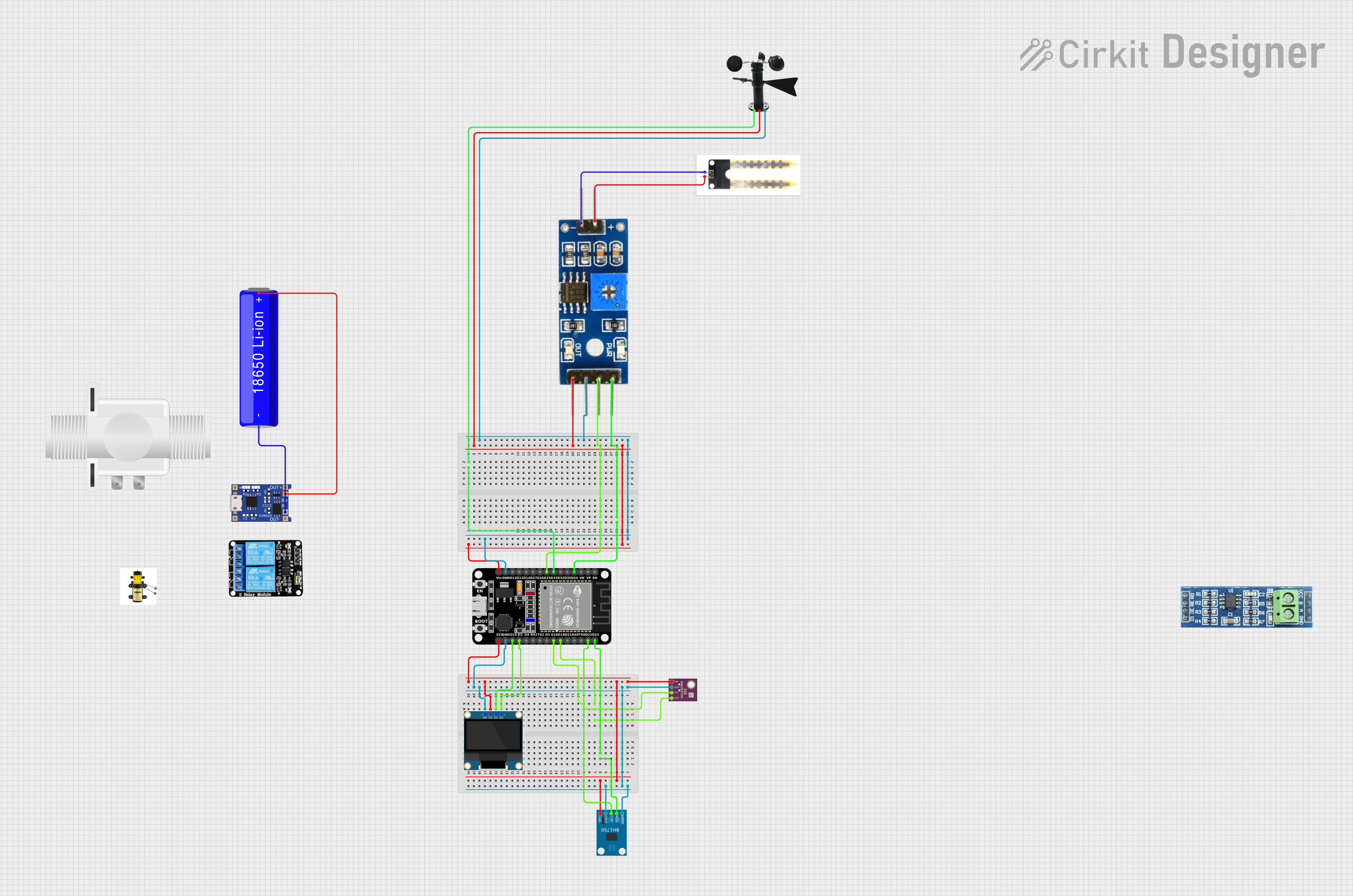

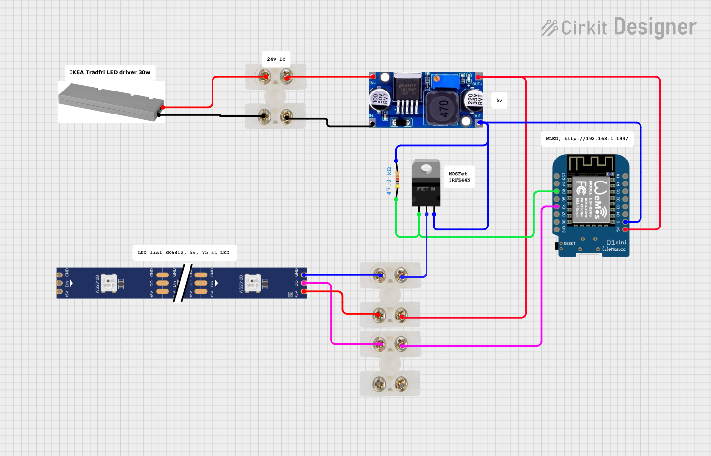
Explore Projects Built with bw16
Common Applications and Use Cases
- Microcontroller-to-microcontroller communication
- Memory interfacing in embedded systems
- Data buffering and level shifting
- Bidirectional communication in digital buses
- General-purpose data transfer in electronic circuits
Technical Specifications
The BW16 is a robust and versatile component with the following key specifications:
| Parameter | Value |
|---|---|
| Operating Voltage | 2.7V to 5.5V |
| Input Voltage Range | 0V to 5.5V |
| Output Voltage Range | 0V to Vcc |
| Maximum Output Current | ±24mA per pin |
| Propagation Delay | 5ns (typical) |
| Operating Temperature | -40°C to +85°C |
| Package Type | TSSOP, SOIC, or DIP |
Pin Configuration and Descriptions
The BW16 has 20 pins, with the following configuration:
| Pin Number | Pin Name | Description |
|---|---|---|
| 1-8 | A1-A8 | Data bus A (lower byte) |
| 9 | GND | Ground |
| 10 | DIR | Direction control (High: A to B, Low: B to A) |
| 11 | OE | Output enable (Active Low) |
| 12-19 | B1-B8 | Data bus B (lower byte) |
| 20 | Vcc | Power supply |
For the 16-bit operation, two BW16 chips can be used in parallel, with one handling the lower byte (A1-A8, B1-B8) and the other handling the upper byte (A9-A16, B9-B16).
Usage Instructions
How to Use the BW16 in a Circuit
- Power Supply: Connect the Vcc pin to a stable power source (2.7V to 5.5V) and the GND pin to the ground.
- Data Buses: Connect the A and B data buses to the respective devices. Ensure that the voltage levels on both sides are compatible with the BW16's operating range.
- Direction Control: Use the DIR pin to set the data flow direction:
- High: Data flows from A to B.
- Low: Data flows from B to A.
- Output Enable: Use the OE pin to enable or disable the outputs:
- Low: Outputs are enabled.
- High: Outputs are in high-impedance state (disabled).
- Pull-Up Resistors: If required, use pull-up resistors on the data lines to ensure proper logic levels when the bus is idle.
Important Considerations and Best Practices
- Ensure that the DIR pin is set correctly before enabling the outputs to avoid bus contention.
- Avoid exceeding the maximum voltage and current ratings to prevent damage to the component.
- Use decoupling capacitors (e.g., 0.1µF) near the Vcc pin to stabilize the power supply.
- For high-speed applications, minimize trace lengths and use proper PCB layout techniques to reduce noise and signal degradation.
Example: Connecting BW16 to an Arduino UNO
The BW16 can be used to interface an Arduino UNO with another device. Below is an example code snippet to control the DIR and OE pins:
// Define pin connections for BW16
const int DIR_PIN = 2;  // Direction control pin
const int OE_PIN = 3;   // Output enable pin

void setup() {
  // Set DIR and OE pins as outputs
  pinMode(DIR_PIN, OUTPUT);
  pinMode(OE_PIN, OUTPUT);

  // Initialize BW16
  digitalWrite(OE_PIN, LOW);  // Enable outputs
  digitalWrite(DIR_PIN, HIGH); // Set direction: A to B
}

void loop() {
  // Example: Toggle direction every 2 seconds
  digitalWrite(DIR_PIN, HIGH); // A to B
  delay(2000);                 // Wait for 2 seconds
  digitalWrite(DIR_PIN, LOW);  // B to A
  delay(2000);                 // Wait for 2 seconds
}
Troubleshooting and FAQs
Common Issues and Solutions
No Data Transfer
- Cause: OE pin is not set correctly.
- Solution: Ensure the OE pin is set to LOW to enable the outputs.
Incorrect Data Direction
- Cause: DIR pin is not configured properly.
- Solution: Verify the DIR pin logic level and ensure it matches the desired data flow direction.
Bus Contention
- Cause: Both devices are driving the bus simultaneously.
- Solution: Use the DIR pin to control the data flow direction and avoid simultaneous driving.
Signal Degradation
- Cause: Long trace lengths or poor PCB layout.
- Solution: Minimize trace lengths and use proper grounding and decoupling techniques.
FAQs
Q1: Can the BW16 handle mixed voltage levels on the A and B buses?
A1: Yes, the BW16 can handle different voltage levels on the A and B buses, provided they are within the specified operating range.
Q2: What happens if the OE pin is left floating?
A2: The OE pin should not be left floating. It must be pulled LOW to enable the outputs or HIGH to disable them.
Q3: Can I use the BW16 for unidirectional communication?
A3: Yes, the BW16 can be used for unidirectional communication by fixing the DIR pin to a specific logic level.
Q4: Is the BW16 suitable for high-speed data transfer?
A4: Yes, the BW16 supports high-speed data transfer with a typical propagation delay of 5ns, making it suitable for most digital applications.