Cirkit Designer Logo
Cirkit Designer
Your all-in-one circuit design IDE
Home / 
Component Documentation

How to Use SYN115: Examples, Pinouts, and Specs

Image of SYN115
Cirkit Designer LogoDesign with SYN115 in Cirkit Designer

Introduction

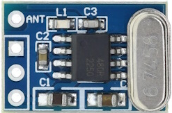
The SYN115 is an electrically conductive synapse chip designed for wireless communication applications. Manufactured by AEAK, the SYN115, in conjunction with its counterpart, the SYN480R receiver chip, is commonly used in remote control systems, telemetry, and other RF communication systems. Its ease of use and low power consumption make it a popular choice for hobbyists and professionals alike.

Explore Projects Built with SYN115

Use Cirkit Designer to design, explore, and prototype these projects online. Some projects support real-time simulation. Click "Open Project" to start designing instantly!
Arduino UNO Controlled RF Transmitter
Image of SYN115 with Arduino: A project utilizing SYN115 in a practical application
This circuit connects an Arduino UNO microcontroller to a SYN115 RF transmitter module. The Arduino provides 5V power and ground to the SYN115, and it is configured to communicate with the SYN115 using digital pin D3. The purpose of this circuit is likely to send RF signals controlled by the Arduino.
Cirkit Designer LogoOpen Project in Cirkit Designer
Beelink Mini S12 N95 and Arduino UNO Based Fingerprint Authentication System with ESP32 CAM
Image of design 3: A project utilizing SYN115 in a practical application
This circuit features a Beelink MINI S12 N95 computer connected to a 7-inch display via HDMI for video output and two USB connections for power and touch screen functionality. An Arduino UNO is interfaced with a fingerprint scanner for biometric input. The Beelink MINI S12 N95 is powered by a PC power supply, which in turn is connected to a 240V power source. Additionally, an ESP32 CAM module is powered and programmed via a USB plug and an FTDI programmer, respectively, for wireless camera capabilities.
Cirkit Designer LogoOpen Project in Cirkit Designer
Satellite-Based Timing and Navigation System with SDR and Atomic Clock Synchronization
Image of GPS 시스템 측정 구성도_Confirm: A project utilizing SYN115 in a practical application
This circuit appears to be a complex system involving power supply management, GPS and timing synchronization, and data communication. It includes a SI-TEX G1 Satellite Compass for GPS data, an XHTF1021 Atomic Rubidium Clock for precise timing, and Ettus USRP B200 units for software-defined radio communication. Power is supplied through various SMPS units and distributed via terminal blocks and DC jacks. Data communication is facilitated by Beelink MINI S12 N95 computers, RS232 splitters, and a 1000BASE-T Media Converter for network connectivity. RF Directional Couplers are used to interface antennas with the USRP units, and the entire system is likely contained within cases for protection and organization.
Cirkit Designer LogoOpen Project in Cirkit Designer
Arduino Mega 2560 Smart Lock System with Ethernet and Touchscreen Control
Image of Copy of SMART LOCK FINAL LAYOUT picture only: A project utilizing SYN115 in a practical application
This circuit is a control system featuring an Arduino Mega 2560 that interfaces with a touchscreen display, an Ethernet module, and a solenoid lock. The system is powered by a 12V power supply with buck converters stepping down the voltage for various components, and it includes a relay to control the solenoid lock.
Cirkit Designer LogoOpen Project in Cirkit Designer

Explore Projects Built with SYN115

Use Cirkit Designer to design, explore, and prototype these projects online. Some projects support real-time simulation. Click "Open Project" to start designing instantly!
Image of SYN115 with Arduino: A project utilizing SYN115 in a practical application
Arduino UNO Controlled RF Transmitter
This circuit connects an Arduino UNO microcontroller to a SYN115 RF transmitter module. The Arduino provides 5V power and ground to the SYN115, and it is configured to communicate with the SYN115 using digital pin D3. The purpose of this circuit is likely to send RF signals controlled by the Arduino.
Cirkit Designer LogoOpen Project in Cirkit Designer
Image of design 3: A project utilizing SYN115 in a practical application
Beelink Mini S12 N95 and Arduino UNO Based Fingerprint Authentication System with ESP32 CAM
This circuit features a Beelink MINI S12 N95 computer connected to a 7-inch display via HDMI for video output and two USB connections for power and touch screen functionality. An Arduino UNO is interfaced with a fingerprint scanner for biometric input. The Beelink MINI S12 N95 is powered by a PC power supply, which in turn is connected to a 240V power source. Additionally, an ESP32 CAM module is powered and programmed via a USB plug and an FTDI programmer, respectively, for wireless camera capabilities.
Cirkit Designer LogoOpen Project in Cirkit Designer
Image of GPS 시스템 측정 구성도_Confirm: A project utilizing SYN115 in a practical application
Satellite-Based Timing and Navigation System with SDR and Atomic Clock Synchronization
This circuit appears to be a complex system involving power supply management, GPS and timing synchronization, and data communication. It includes a SI-TEX G1 Satellite Compass for GPS data, an XHTF1021 Atomic Rubidium Clock for precise timing, and Ettus USRP B200 units for software-defined radio communication. Power is supplied through various SMPS units and distributed via terminal blocks and DC jacks. Data communication is facilitated by Beelink MINI S12 N95 computers, RS232 splitters, and a 1000BASE-T Media Converter for network connectivity. RF Directional Couplers are used to interface antennas with the USRP units, and the entire system is likely contained within cases for protection and organization.
Cirkit Designer LogoOpen Project in Cirkit Designer
Image of Copy of SMART LOCK FINAL LAYOUT picture only: A project utilizing SYN115 in a practical application
Arduino Mega 2560 Smart Lock System with Ethernet and Touchscreen Control
This circuit is a control system featuring an Arduino Mega 2560 that interfaces with a touchscreen display, an Ethernet module, and a solenoid lock. The system is powered by a 12V power supply with buck converters stepping down the voltage for various components, and it includes a relay to control the solenoid lock.
Cirkit Designer LogoOpen Project in Cirkit Designer

Common Applications and Use Cases

  • Remote control systems
  • Wireless data transmission
  • Telemetry and sensor networks
  • Home automation
  • DIY electronics projects

Technical Specifications

Key Technical Details

  • Operating Frequency: 315MHz / 433MHz (depending on the model)
  • Supply Voltage: 2.0V to 3.6V
  • Operating Current: 11mA (typical at 3V)
  • Modulation: ASK/OOK
  • Output Power: Up to +10dBm

Pin Configuration and Descriptions

Pin Number Name Description
1 ANT Antenna connection
2 VDD Power supply (2.0V to 3.6V)
3 GND Ground
4 DATA Data input for modulation

Usage Instructions

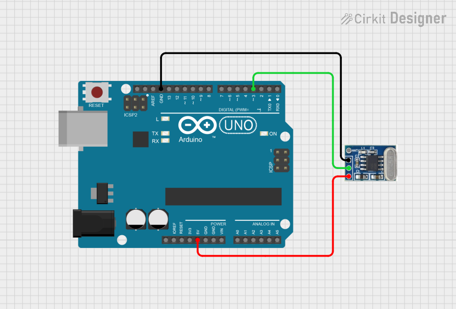
How to Use the SYN115 in a Circuit

  1. Power Supply: Connect the VDD pin to a power source between 2.0V and 3.6V. Ensure that the power supply is stable and clean.
  2. Grounding: Connect the GND pin to the ground of your circuit.
  3. Antenna: Attach an appropriate antenna to the ANT pin for signal transmission. The length of the antenna should correspond to the operating frequency (typically a quarter wavelength).
  4. Data Input: The DATA pin is used to input the signal you wish to transmit. This can be a digital signal from a microcontroller or another digital device.

Important Considerations and Best Practices

  • Ensure that the power supply does not exceed the maximum voltage rating.
  • Use a decoupling capacitor close to the VDD pin to filter out power supply noise.
  • Keep the antenna clear of metal objects to avoid interference.
  • Follow local regulations regarding RF transmission power and frequency usage.

Example Code for Arduino UNO

// Example code for transmitting data using SYN115 with an Arduino UNO
#include <VirtualWire.h>

const int txPin = 12; // Connect to the DATA pin of SYN115

void setup() {
  vw_set_tx_pin(txPin); // Set the VirtualWire transmit pin
  vw_setup(2000);       // Bits per sec
}

void loop() {
  const char *msg = "Hello World";
  vw_send((uint8_t *)msg, strlen(msg)); // Send the message
  vw_wait_tx(); // Wait until the whole message is gone
  delay(1000); // Wait for a second before sending the next message
}

Troubleshooting and FAQs

Common Issues

  • No Signal Transmission: Ensure the antenna is properly connected and the power supply is within the specified range.
  • Weak Signal: Check the antenna placement and length. Make sure there are no obstructions or interference sources nearby.
  • Intermittent Operation: Verify that all connections are secure and there is no intermittent contact, especially at the DATA pin.

Solutions and Tips for Troubleshooting

  • Always double-check wiring and solder joints for a solid connection.
  • Use a spectrum analyzer or RF power meter to verify the output power and frequency of the SYN115.
  • If experiencing interference, try changing the operating frequency if your model supports it.

FAQs

Q: Can I use the SYN115 with a 5V power supply? A: No, the SYN115 is rated for a maximum of 3.6V. Exceeding this voltage can damage the chip.

Q: What is the range of the SYN115? A: The range depends on many factors, including the antenna design, operating environment, and power supply. Under ideal conditions, it can reach up to 100 meters.

Q: Is the SYN115 legal to use in my country? A: RF regulations vary by country. Check your local regulations to ensure compliance with transmission power and frequency use.

Q: Can I use the SYN115 for continuous data transmission? A: Yes, but ensure that the duty cycle and heat dissipation are within the chip's operating limits to avoid overheating.

For further assistance, please contact AEAK support or refer to the SYN115 datasheet for more detailed information.