Cirkit Designer
Your all-in-one circuit design IDE
Home /
Component Documentation
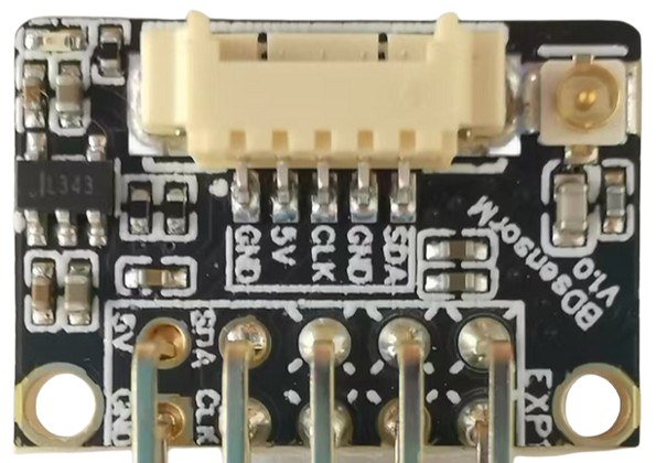
How to Use BD Sensor Board: Examples, Pinouts, and Specs
Introduction
The BD Sensor Board is a versatile circuit board that integrates various sensors to detect and measure physical properties such as temperature, pressure, humidity, and motion. This board is commonly used in applications requiring environmental monitoring and data collection. Its compact design and ease of integration make it suitable for a wide range of projects, from home automation systems to industrial monitoring solutions.
Explore Projects Built with BD Sensor Board
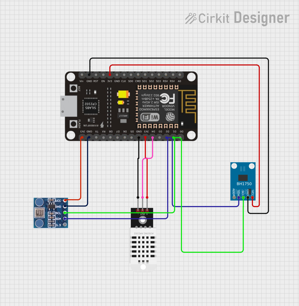
ESP32-Based Environmental Monitoring System with Motion Detection

This circuit features an ESP32 microcontroller on a baseboard that interfaces with a PIR sensor for motion detection, a DHT22 sensor for measuring temperature and humidity, and a BH1750 sensor for detecting ambient light levels. The ESP32 is configured to communicate with the BH1750 using I2C protocol, with GPIO22 and GPIO21 serving as the SCL and SDA lines, respectively. Power is supplied to the sensors from the ESP32's voltage output pins, and sensor outputs are connected to designated GPIO pins for data acquisition.
ESP-8266 Based Environmental Monitoring System
This circuit features an ESP-8266 microcontroller connected to a BMP180 barometric pressure sensor, a BH1750 light intensity sensor, and a DHT22 temperature and humidity sensor. The ESP-8266 uses its I2C interface, with pins D1 and D2 connected to the SCL and SDA lines of both the BMP180 and BH1750, to communicate with the sensors. The DHT22 sensor is connected to a digital pin (D4) for direct signal reading, and all sensors share common power (3V3) and ground (GND) connections with the microcontroller.
ESP8266-Based Health Monitoring System with OLED Display
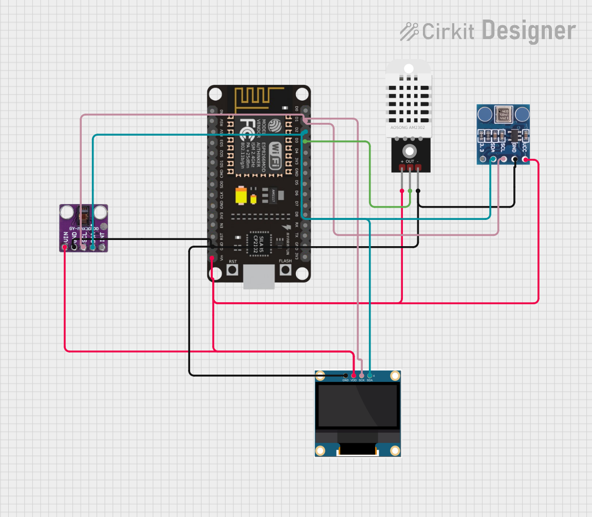
This circuit is a multi-sensor data acquisition system using an ESP8266 NodeMCU microcontroller. It integrates a MAX30100 pulse oximeter, a BMP180 barometric pressure sensor, a DHT22 temperature and humidity sensor, and a 0.96" OLED display for real-time data visualization. The sensors communicate with the microcontroller via I2C and digital interfaces, and the collected data is displayed on the OLED screen.
ESP32-Based Environmental Sensing Station with Wi-Fi and Light Intensity Measurement
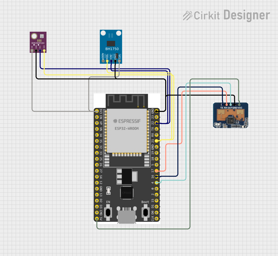
This circuit is designed to collect environmental data and light intensity measurements using the ESP32 microcontroller, which communicates with a BME/BMP280 sensor and a BH1750 sensor via I2C, and transmits the data through an LD2410C communication module using serial communication.
Explore Projects Built with BD Sensor Board
ESP32-Based Environmental Monitoring System with Motion Detection
This circuit features an ESP32 microcontroller on a baseboard that interfaces with a PIR sensor for motion detection, a DHT22 sensor for measuring temperature and humidity, and a BH1750 sensor for detecting ambient light levels. The ESP32 is configured to communicate with the BH1750 using I2C protocol, with GPIO22 and GPIO21 serving as the SCL and SDA lines, respectively. Power is supplied to the sensors from the ESP32's voltage output pins, and sensor outputs are connected to designated GPIO pins for data acquisition.
ESP-8266 Based Environmental Monitoring System
This circuit features an ESP-8266 microcontroller connected to a BMP180 barometric pressure sensor, a BH1750 light intensity sensor, and a DHT22 temperature and humidity sensor. The ESP-8266 uses its I2C interface, with pins D1 and D2 connected to the SCL and SDA lines of both the BMP180 and BH1750, to communicate with the sensors. The DHT22 sensor is connected to a digital pin (D4) for direct signal reading, and all sensors share common power (3V3) and ground (GND) connections with the microcontroller.
ESP8266-Based Health Monitoring System with OLED Display
This circuit is a multi-sensor data acquisition system using an ESP8266 NodeMCU microcontroller. It integrates a MAX30100 pulse oximeter, a BMP180 barometric pressure sensor, a DHT22 temperature and humidity sensor, and a 0.96" OLED display for real-time data visualization. The sensors communicate with the microcontroller via I2C and digital interfaces, and the collected data is displayed on the OLED screen.
ESP32-Based Environmental Sensing Station with Wi-Fi and Light Intensity Measurement
This circuit is designed to collect environmental data and light intensity measurements using the ESP32 microcontroller, which communicates with a BME/BMP280 sensor and a BH1750 sensor via I2C, and transmits the data through an LD2410C communication module using serial communication.
Technical Specifications
Key Technical Details
| Parameter | Value |
|---|---|
| Operating Voltage | 3.3V - 5V |
| Operating Current | 10mA - 50mA |
| Temperature Range | -40°C to 85°C |
| Humidity Range | 0% to 100% RH |
| Pressure Range | 300 hPa to 1100 hPa |
| Motion Detection | Up to 10 meters |
| Communication | I2C, SPI |
Pin Configuration and Descriptions
| Pin Number | Pin Name | Description |
|---|---|---|
| 1 | VCC | Power supply (3.3V - 5V) |
| 2 | GND | Ground |
| 3 | SDA | I2C Data Line |
| 4 | SCL | I2C Clock Line |
| 5 | MISO | SPI Master In Slave Out |
| 6 | MOSI | SPI Master Out Slave In |
| 7 | SCK | SPI Clock |
| 8 | CS | Chip Select for SPI |
| 9 | INT | Interrupt Pin for Motion Detection |
| 10 | A0 | Analog Output for Temperature Sensor |
Usage Instructions
How to Use the Component in a Circuit
- Power Supply: Connect the VCC pin to a 3.3V or 5V power supply and the GND pin to the ground.
- Communication Interface: Choose between I2C or SPI for communication.
- For I2C, connect the SDA and SCL pins to the corresponding pins on your microcontroller.
- For SPI, connect the MISO, MOSI, SCK, and CS pins to the corresponding pins on your microcontroller.
- Sensor Readings: Use the analog output (A0) for temperature readings and the interrupt pin (INT) for motion detection alerts.
Important Considerations and Best Practices
- Power Supply: Ensure that the power supply voltage matches the operating voltage range of the BD Sensor Board.
- Pull-up Resistors: When using I2C communication, make sure to use appropriate pull-up resistors on the SDA and SCL lines.
- Noise Reduction: Place decoupling capacitors close to the power supply pins to reduce noise and improve stability.
- Sensor Placement: Position the board in a location where it can accurately measure the desired environmental parameters without interference.
Example Code for Arduino UNO
#include <Wire.h>  // Include Wire library for I2C communication

#define TEMP_SENSOR_ADDR 0x48  // I2C address for temperature sensor
#define MOTION_SENSOR_PIN 2    // Digital pin for motion sensor interrupt

void setup() {
  Serial.begin(9600);  // Initialize serial communication at 9600 baud rate
  Wire.begin();        // Initialize I2C communication
  pinMode(MOTION_SENSOR_PIN, INPUT);  // Set motion sensor pin as input
  attachInterrupt(digitalPinToInterrupt(MOTION_SENSOR_PIN), motionDetected, RISING);
  // Attach interrupt to motion sensor pin, trigger on rising edge
}

void loop() {
  float temperature = readTemperature();  // Read temperature from sensor
  Serial.print("Temperature: ");
  Serial.print(temperature);
  Serial.println(" C");
  delay(1000);  // Wait for 1 second before next reading
}

float readTemperature() {
  Wire.beginTransmission(TEMP_SENSOR_ADDR);  // Start I2C transmission
  Wire.write(0x00);  // Send command to read temperature
  Wire.endTransmission();  // End I2C transmission
  Wire.requestFrom(TEMP_SENSOR_ADDR, 2);  // Request 2 bytes from sensor
  if (Wire.available() == 2) {
    int temp = Wire.read() << 8 | Wire.read();  // Read temperature data
    return temp * 0.0625;  // Convert to Celsius
  }
  return 0.0;  // Return 0.0 if no data available
}

void motionDetected() {
  Serial.println("Motion detected!");  // Print message when motion is detected
}
Troubleshooting and FAQs
Common Issues Users Might Face
- No Sensor Readings: Ensure that the power supply is connected correctly and that the communication lines (I2C or SPI) are properly connected.
- Incorrect Temperature Readings: Verify that the sensor is not placed near heat sources or in direct sunlight, which can affect accuracy.
- Motion Detection Not Working: Check the interrupt pin connection and ensure that the motion sensor is within its detection range.
Solutions and Tips for Troubleshooting
- Check Connections: Double-check all connections to ensure they are secure and correctly placed.
- Use Serial Monitor: Utilize the Serial Monitor in the Arduino IDE to debug and verify sensor readings.
- Update Libraries: Ensure that you are using the latest versions of the required libraries (e.g., Wire library for I2C communication).
By following this documentation, users can effectively integrate and utilize the BD Sensor Board in their projects, ensuring accurate environmental monitoring and data collection.