How to Use DFR0816: Examples, Pinouts, and Specs
Introduction
The DFR0816 Leonardo is a compact, low-power microcontroller board developed by DFRobot. It is based on the ATmega32u4 microcontroller and is designed for a wide range of embedded applications. With its multiple I/O ports, built-in communication interfaces, and USB support, the DFR0816 is particularly well-suited for robotics, automation, and IoT projects. Its small form factor and versatility make it an excellent choice for both beginners and experienced developers.
Explore Projects Built with DFR0816
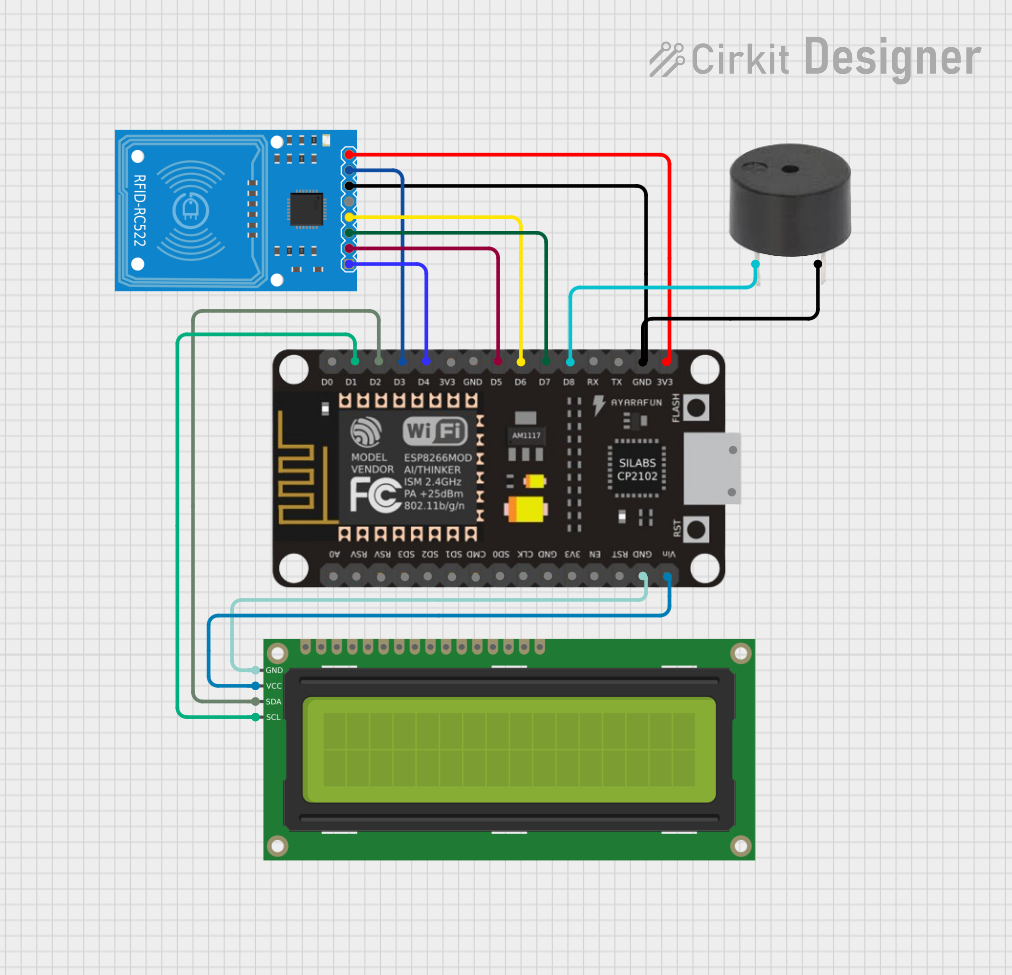


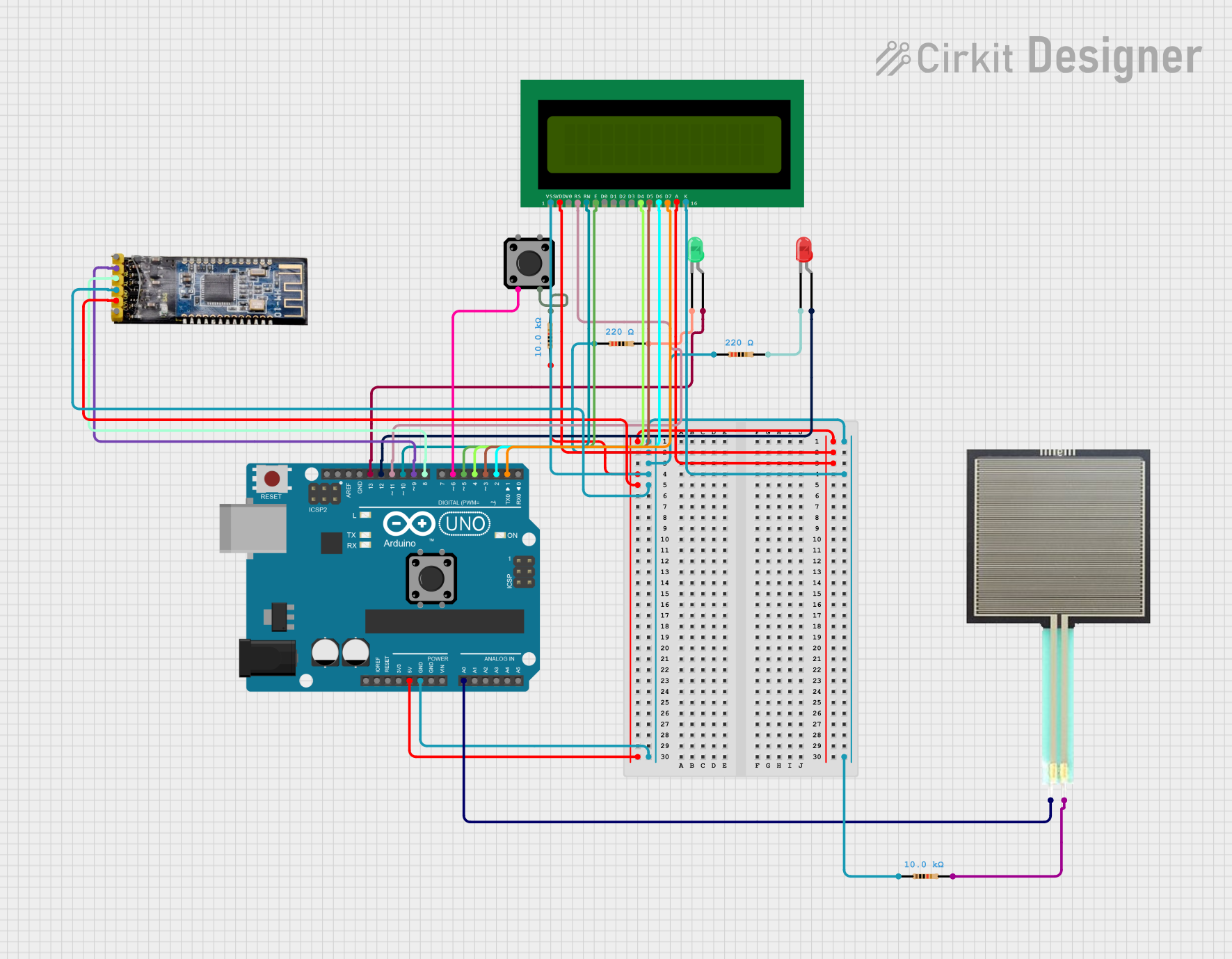
Explore Projects Built with DFR0816
Common Applications and Use Cases
- Robotics control systems
- Home automation projects
- IoT (Internet of Things) devices
- Sensor data acquisition and processing
- Prototyping and educational purposes
Technical Specifications
The DFR0816 Leonardo offers the following key technical features:
| Specification | Details |
|---|---|
| Microcontroller | ATmega32u4 |
| Operating Voltage | 5V |
| Input Voltage (recommended) | 7-12V |
| Digital I/O Pins | 20 (7 PWM outputs) |
| Analog Input Pins | 12 |
| DC Current per I/O Pin | 40 mA |
| Flash Memory | 32 KB (4 KB used by bootloader) |
| SRAM | 2.5 KB |
| EEPROM | 1 KB |
| Clock Speed | 16 MHz |
| Communication Interfaces | UART, I2C, SPI, USB |
| Dimensions | 68.6 mm x 53.4 mm |
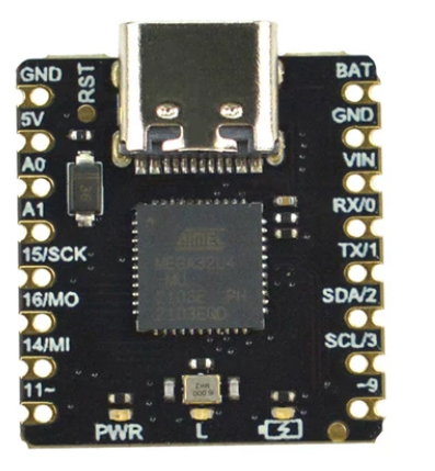
Pin Configuration and Descriptions
The DFR0816 Leonardo features a standard pin layout. Below is a detailed description of its pin configuration:
| Pin | Type | Description |
|---|---|---|
| 0-13 | Digital I/O | General-purpose digital input/output pins |
| 3, 5, 6, 9, 10, 11 | PWM | Pulse Width Modulation outputs |
| A0-A11 | Analog Input | Analog input pins (10-bit resolution) |
| VIN | Power Input | External power supply input (7-12V recommended) |
| 5V | Power Output | Regulated 5V output |
| 3.3V | Power Output | Regulated 3.3V output |
| GND | Ground | Ground connection |
| RESET | Reset | Resets the microcontroller |
| TX/RX | UART | Serial communication pins (Transmit/Receive) |
| SDA | I2C Data | Data line for I2C communication |
| SCL | I2C Clock | Clock line for I2C communication |
| ICSP | SPI | In-Circuit Serial Programming header for SPI |
| USB | USB Interface | Micro-USB port for programming and communication |
Usage Instructions
How to Use the DFR0816 in a Circuit
Powering the Board:
- Connect an external power supply (7-12V) to the VIN pin or use the micro-USB port for power and programming.
- Ensure the power source provides sufficient current for connected peripherals.
Programming the Board:
- Use the Arduino IDE to program the DFR0816 Leonardo. Select "Arduino Leonardo" as the board type in the IDE.
- Connect the board to your computer via the micro-USB cable. The board will appear as a USB device.
Connecting Peripherals:
- Use the digital I/O pins for controlling LEDs, relays, or other digital devices.
- Use the analog input pins to read sensor data (e.g., temperature, light, or pressure sensors).
- For communication, connect devices using UART, I2C, or SPI interfaces.
Uploading Code:
- Write your code in the Arduino IDE and click the "Upload" button. The code will be transferred to the board via USB.
Important Considerations and Best Practices
- Avoid exceeding the maximum current rating (40 mA) for any I/O pin to prevent damage.
- Use appropriate pull-up or pull-down resistors for input pins to ensure stable readings.
- When using the board in noisy environments, consider adding decoupling capacitors to stabilize the power supply.
- Always disconnect power before making changes to the circuit to avoid short circuits or damage.
Example Code for Arduino UNO-Compatible Projects
The following example demonstrates how to blink an LED connected to pin 13:
// Example: Blink an LED connected to pin 13

void setup() {
  pinMode(13, OUTPUT); // Set pin 13 as an output
}

void loop() {
  digitalWrite(13, HIGH); // Turn the LED on
  delay(1000);            // Wait for 1 second
  digitalWrite(13, LOW);  // Turn the LED off
  delay(1000);            // Wait for 1 second
}
Troubleshooting and FAQs
Common Issues and Solutions
The board is not recognized by the computer:
- Ensure the USB cable is properly connected and functional.
- Check that the correct drivers are installed for the DFR0816 Leonardo.
- Try using a different USB port or cable.
Code upload fails:
- Verify that the correct board type ("Arduino Leonardo") is selected in the Arduino IDE.
- Ensure no other application is using the COM port.
- Press the reset button on the board before uploading the code.
The board is not powering on:
- Check the power source and ensure it meets the voltage and current requirements.
- Inspect the board for any visible damage or loose connections.
Analog readings are unstable:
- Use a capacitor (e.g., 0.1 µF) between the analog input pin and ground to filter noise.
- Ensure the sensor or input device is properly grounded.
FAQs
Q: Can the DFR0816 Leonardo be powered via USB alone?
A: Yes, the board can be powered and programmed via the micro-USB port. However, for higher current requirements, use an external power supply.
Q: Is the DFR0816 compatible with Arduino shields?
A: Yes, the DFR0816 Leonardo is compatible with most Arduino shields designed for the Leonardo form factor.
Q: How do I reset the board?
A: Press the reset button on the board, or use the RESET pin to trigger a reset programmatically.
Q: Can I use the DFR0816 for wireless communication?
A: Yes, you can connect wireless modules (e.g., Bluetooth, Wi-Fi) via UART, I2C, or SPI interfaces.
This concludes the documentation for the DFR0816 Leonardo. For further assistance, refer to the official DFRobot resources or community forums.