
How to Use IRF520 MOSFET Module: Examples, Pinouts, and Specs
 Design with IRF520 MOSFET Module in Cirkit Designer
Introduction
The IRF520 MOSFET Module is a power electronic component designed for switching and amplifying electronic signals. It features an N-channel MOSFET capable of handling high voltages and currents, making it ideal for applications such as motor control, power management, and signal amplification. The module is pre-assembled with additional components like resistors and diodes, simplifying its integration into circuits and providing protection during operation.
Explore Projects Built with IRF520 MOSFET Module
 Open Project in Cirkit Designer
 Open Project in Cirkit Designer
 Open Project in Cirkit Designer
 Open Project in Cirkit Designer
Explore Projects Built with IRF520 MOSFET Module
Open Project in Cirkit DesignerOpen Project in Cirkit DesignerOpen Project in Cirkit DesignerOpen Project in Cirkit DesignerCommon Applications
- Motor speed control
- LED dimming and control
- DC-DC converters
- Signal amplification
- Power switching in microcontroller-based projects
Technical Specifications
The IRF520 MOSFET Module is built around the IRF520 N-channel MOSFET and includes supporting components for ease of use. Below are the key technical details:
Key Specifications
| Parameter | Value |
|---|---|
| MOSFET Type | N-channel |
| Operating Voltage | 3.3V to 5V (logic level input) |
| Drain-Source Voltage (Vds) | 100V |
| Continuous Drain Current (Id) | 9.2A (at 25°C) |
| Gate Threshold Voltage (Vgs) | 2.0V to 4.0V |
| Power Dissipation | 40W |
| On-Resistance (Rds(on)) | 0.27Ω (max) |
| Module Dimensions | ~33mm x 25mm x 15mm |
Pin Configuration
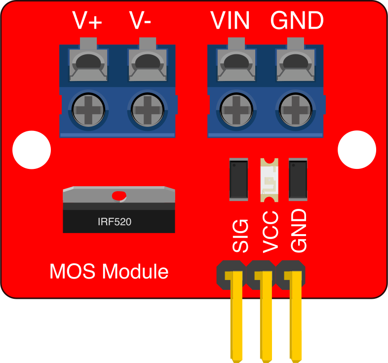
The IRF520 MOSFET Module typically has a 3-pin input interface and a 2-pin output interface. Below is the pin description:
Input Pins
| Pin Name | Description |
|---|---|
| VCC | Connect to the positive supply voltage (3.3V or 5V). |
| GND | Connect to the ground of the power supply. |
| SIG | Signal input pin to control the MOSFET gate. |
Output Pins
| Pin Name | Description |
|---|---|
| V+ | Connect to the positive terminal of the load. |
| V- | Connect to the negative terminal of the load. |
Usage Instructions
How to Use the IRF520 MOSFET Module in a Circuit
- Power Supply Connection: Connect the
VCCpin to a 3.3V or 5V power source and theGNDpin to the ground of the same power source. - Signal Input: Connect the
SIGpin to a microcontroller's GPIO pin or any other control signal source. Ensure the signal voltage matches the module's input voltage range (3.3V to 5V). - Load Connection: Connect the load (e.g., motor, LED, or other devices) between the
V+andV-pins. Ensure the load's voltage and current requirements are within the module's specifications. - Control the Load: Use the control signal on the
SIGpin to switch the load on or off. A HIGH signal (3.3V or 5V) will turn the MOSFET on, allowing current to flow through the load.
Important Considerations
- Heat Dissipation: The MOSFET can generate heat during operation, especially at high currents. Use a heatsink if necessary to prevent overheating.
- Voltage Spikes: For inductive loads (e.g., motors), ensure the module's built-in flyback diode is functional to protect against voltage spikes.
- Signal Voltage: Ensure the control signal voltage is within the module's operating range (3.3V to 5V). Using a higher voltage may damage the module.
Example: Controlling an LED with Arduino UNO
Below is an example of how to use the IRF520 MOSFET Module to control an LED with an Arduino UNO:
// Define the pin connected to the SIG pin of the IRF520 module
const int mosfetPin = 9;

void setup() {
  // Set the MOSFET control pin as an output
  pinMode(mosfetPin, OUTPUT);
}

void loop() {
  // Turn the LED on by sending a HIGH signal to the MOSFET
  digitalWrite(mosfetPin, HIGH);
  delay(1000); // Keep the LED on for 1 second

  // Turn the LED off by sending a LOW signal to the MOSFET
  digitalWrite(mosfetPin, LOW);
  delay(1000); // Keep the LED off for 1 second
}
Notes:
- Ensure the LED's current and voltage ratings are within the module's specifications.
- Use a current-limiting resistor in series with the LED to prevent damage.
Troubleshooting and FAQs
Common Issues and Solutions
The load does not turn on:
- Verify that the
SIGpin is receiving the correct control signal (3.3V or 5V). - Check the connections to ensure the load is properly connected to the
V+andV-pins. - Ensure the load's voltage and current requirements are within the module's specifications.
- Verify that the
The MOSFET overheats:
- Check if the load's current exceeds the MOSFET's maximum current rating (9.2A).
- Use a heatsink to dissipate heat if the MOSFET operates at high currents for extended periods.
The module does not respond to the control signal:
- Ensure the
VCCandGNDpins are properly connected to the power supply. - Verify that the control signal voltage matches the module's input voltage range (3.3V to 5V).
- Ensure the
Voltage spikes damage the module:
- For inductive loads, ensure the module's built-in flyback diode is functional.
- Consider adding an external flyback diode across the load for additional protection.
FAQs
Q: Can the IRF520 MOSFET Module handle AC loads?
A: No, the IRF520 MOSFET Module is designed for DC loads only. Using it with AC loads may damage the module.
Q: Can I use the module with a 12V control signal?
A: No, the module's control signal input is designed for 3.3V to 5V logic levels. Using a 12V signal may damage the module.
Q: Is the module suitable for PWM control?
A: Yes, the IRF520 MOSFET Module can be used for PWM (Pulse Width Modulation) control, making it ideal for applications like motor speed control and LED dimming.
Q: Do I need an external resistor for the gate?
A: No, the module includes a built-in resistor for the gate, so no external resistor is required.
By following this documentation, you can effectively use the IRF520 MOSFET Module in your projects while avoiding common pitfalls.