How to Use DWIN_240*960_BarLCD: Examples, Pinouts, and Specs
Introduction
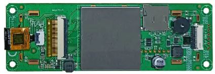
The DWIN_240*960_BarLCD (Manufacturer Part ID: DMG96240C037_03W) is a high-resolution bar LCD display module designed for applications requiring a compact yet visually impactful display. With a resolution of 240x960 pixels, this module is ideal for industrial control panels, automotive dashboards, smart home devices, and other embedded systems. Manufactured by DWIN, this display offers excellent clarity, wide viewing angles, and reliable performance.
Explore Projects Built with DWIN_240*960_BarLCD

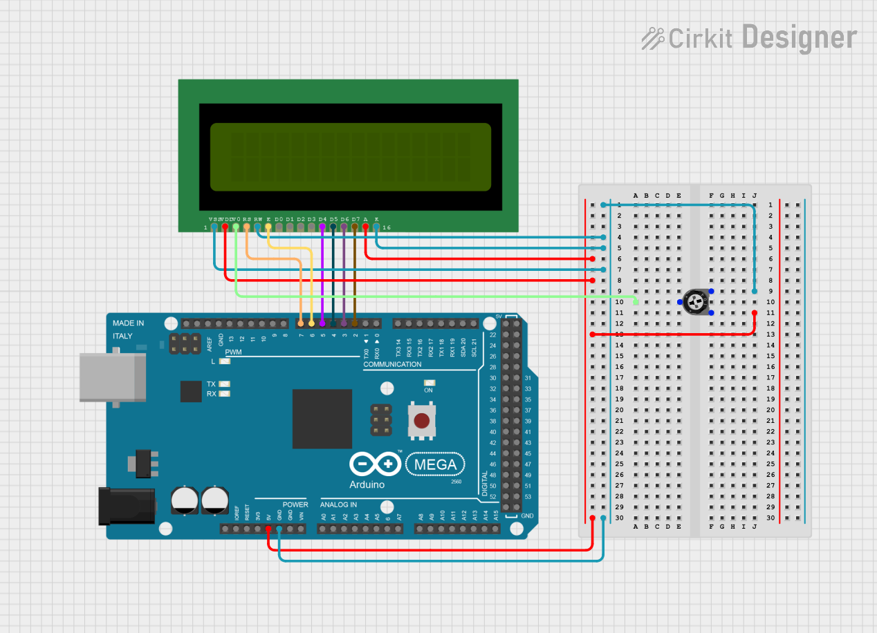
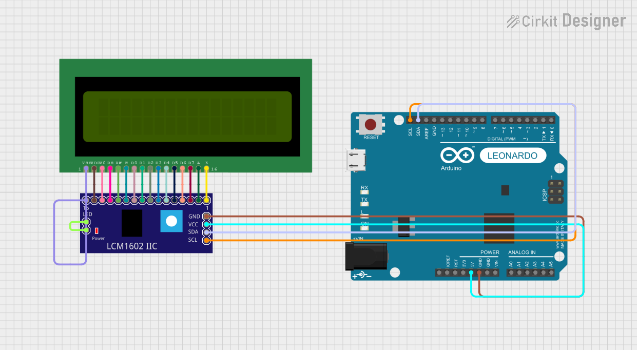

Explore Projects Built with DWIN_240*960_BarLCD
Common Applications
- Industrial control systems
- Automotive dashboards and infotainment systems
- Smart home devices and IoT displays
- Medical equipment interfaces
- Consumer electronics with narrow display requirements
Technical Specifications
Key Technical Details
| Parameter | Specification |
|---|---|
| Manufacturer | DWIN |
| Part ID | DMG96240C037_03W |
| Display Resolution | 240 x 960 pixels |
| Display Type | TFT LCD |
| Active Area | 37.152 mm x 148.608 mm |
| Aspect Ratio | 1:4 |
| Interface | UART / RS232 / TTL |
| Operating Voltage | 5V DC |
| Operating Temperature | -20°C to 70°C |
| Backlight | LED |
| Viewing Angle | Wide (All Directions) |
| Touchscreen Support | Optional (Capacitive Touchscreen) |
Pin Configuration and Descriptions
The DWIN_240*960_BarLCD module typically uses a 10-pin interface for communication and power. Below is the pin configuration:
| Pin Number | Pin Name | Description |
|---|---|---|
| 1 | VCC | Power supply input (5V DC) |
| 2 | GND | Ground |
| 3 | RX | UART Receive (Data input to the display) |
| 4 | TX | UART Transmit (Data output from the display) |
| 5 | RESET | Reset pin (Active Low) |
| 6 | NC | Not Connected |
| 7 | NC | Not Connected |
| 8 | NC | Not Connected |
| 9 | BL_CTRL | Backlight control (PWM or ON/OFF) |
| 10 | TOUCH_INT | Touchscreen interrupt signal (if touchscreen) |
Usage Instructions
How to Use the Component in a Circuit
- Power Supply: Connect the VCC pin to a regulated 5V DC power source and the GND pin to the ground of your circuit.
- Communication: Use the RX and TX pins to establish UART communication with a microcontroller or host device. Ensure the baud rate matches the display's configuration (default is typically 115200 bps).
- Backlight Control: Use the BL_CTRL pin to control the backlight. This can be done via a PWM signal for brightness adjustment or a simple HIGH/LOW signal for ON/OFF control.
- Reset: Connect the RESET pin to a GPIO pin on your microcontroller for manual or software-controlled resets.
- Touchscreen (Optional): If the module includes a capacitive touchscreen, connect the TOUCH_INT pin to a GPIO pin to handle touch interrupts.
Important Considerations and Best Practices
- Voltage Levels: Ensure the UART communication voltage levels are compatible with the display (typically 3.3V or 5V).
- Baud Rate: Verify and configure the correct baud rate for UART communication.
- ESD Protection: Use proper ESD protection measures to prevent damage to the display module.
- Mounting: Secure the display module in your enclosure to avoid mechanical stress on the pins or the screen.
- Backlight Lifetime: Avoid running the backlight at maximum brightness for extended periods to prolong its lifespan.
Example Code for Arduino UNO
Below is an example of how to interface the DWIN_240*960_BarLCD with an Arduino UNO using UART communication:
#include <SoftwareSerial.h>

// Define RX and TX pins for SoftwareSerial
SoftwareSerial mySerial(10, 11); // RX, TX

void setup() {
  // Initialize serial communication
  Serial.begin(9600); // For debugging via Serial Monitor
  mySerial.begin(115200); // Communication with the DWIN display

  // Send initialization command to the display
  mySerial.write(0xAA); // Example command to initialize the display
  mySerial.write(0xBB); // Replace with actual initialization sequence
  Serial.println("DWIN Display Initialized");
}

void loop() {
  // Example: Send a command to display text
  mySerial.write(0x5A); // Command header
  mySerial.write(0x01); // Command to display text
  mySerial.write("Hello, World!"); // Text to display
  delay(1000); // Wait for 1 second

  // Example: Clear the display
  mySerial.write(0x5A); // Command header
  mySerial.write(0x02); // Command to clear the display
  delay(1000); // Wait for 1 second
}
Troubleshooting and FAQs
Common Issues and Solutions
Display Not Turning On
- Cause: Incorrect power supply or loose connections.
- Solution: Verify the power supply voltage (5V DC) and ensure all connections are secure.
No Communication with Microcontroller
- Cause: Incorrect UART baud rate or wiring.
- Solution: Check the baud rate configuration and ensure RX/TX pins are correctly connected.
Backlight Not Working
- Cause: BL_CTRL pin not properly configured.
- Solution: Ensure the BL_CTRL pin is set to HIGH for backlight ON or provide a PWM signal for brightness control.
Touchscreen Not Responding
- Cause: TOUCH_INT pin not connected or firmware issue.
- Solution: Verify the TOUCH_INT connection and ensure the microcontroller is configured to handle touch interrupts.
FAQs
Can I use this display with a 3.3V microcontroller?
- Yes, but you may need a level shifter for UART communication if the display operates at 5V logic levels.
What is the default baud rate for UART communication?
- The default baud rate is typically 115200 bps, but refer to the manufacturer's datasheet for confirmation.
Is the touchscreen mandatory for operation?
- No, the touchscreen is optional and only required if your application needs touch input.
How do I update the firmware on the display?
- Firmware updates can typically be performed via the UART interface. Refer to the manufacturer's documentation for detailed instructions.
By following this documentation, you can effectively integrate the DWIN_240*960_BarLCD into your projects and troubleshoot common issues with ease.