Cirkit Designer Logo
Cirkit Designer
Your all-in-one circuit design IDE
Home / 
Component Documentation

How to Use Adafruit Seven-Segment LED Backpack 1.2 Inch Digits Green: Examples, Pinouts, and Specs

Image of Adafruit Seven-Segment LED Backpack 1.2 Inch Digits Green
Cirkit Designer LogoDesign with Adafruit Seven-Segment LED Backpack 1.2 Inch Digits Green in Cirkit Designer

Introduction

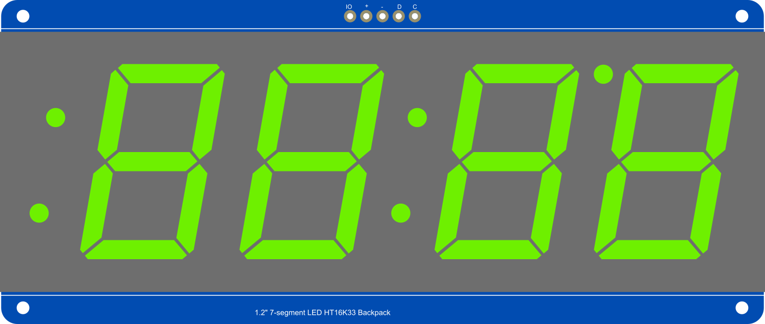
The Adafruit Seven-Segment LED Backpack 1.2 Inch Digits Green is a user-friendly display module designed for numeric output visualization. It features four 1.2-inch tall green seven-segment LEDs, which are bright, clear, and visible from a distance. The integrated I2C backpack reduces the number of necessary pins to control the display, making it perfect for projects with limited GPIO availability. Common applications include clocks, counters, and readouts for sensors.

Explore Projects Built with Adafruit Seven-Segment LED Backpack 1.2 Inch Digits Green

Use Cirkit Designer to design, explore, and prototype these projects online. Some projects support real-time simulation. Click "Open Project" to start designing instantly!
Arduino UNO Controlled LED and 7-Segment Display Circuit
Image of Beunen aan water: A project utilizing Adafruit Seven-Segment LED Backpack 1.2 Inch Digits Green in a practical application
This circuit features an Arduino UNO controlling multiple blue LEDs and a 4-digit 7-segment display. The LEDs are configured with current-limiting resistors, and the display is interfaced with the Arduino for potential numeric or character output. The provided code for the Arduino is a template without specific functionality.
Cirkit Designer LogoOpen Project in Cirkit Designer
74HC21-Based LED Display with 7-Segment Indicator
Image of FPGA Exp. 1: A project utilizing Adafruit Seven-Segment LED Backpack 1.2 Inch Digits Green in a practical application
This circuit is a digital display system that uses a 7-segment display and multiple red LEDs controlled by 74HC21 logic gates and DIP switches. The LEDs are connected through resistors to the logic gates, which are powered by a DC power source, allowing for the display of various states or numbers based on the DIP switch settings.
Cirkit Designer LogoOpen Project in Cirkit Designer
Battery-Powered Sensor Hub with Adafruit QT Py RP2040 and OLED Display
Image of 512: A project utilizing Adafruit Seven-Segment LED Backpack 1.2 Inch Digits Green in a practical application
This circuit features an Adafruit QT Py RP2040 microcontroller interfacing with an MPU-6050 accelerometer, an Adafruit APDS-9960 sensor, and a 0.96" OLED display via I2C communication. It is powered by a 3.7V LiPo battery and includes a green LED with a current-limiting resistor connected to an analog pin of the microcontroller.
Cirkit Designer LogoOpen Project in Cirkit Designer
Arduino UNO Controlled Seven-Segment Display Counter
Image of Arduino Uno - Seven Segment Display (Sim-C): A project utilizing Adafruit Seven-Segment LED Backpack 1.2 Inch Digits Green in a practical application
This circuit uses an Arduino UNO to control a seven-segment display, displaying digits from 0 to 9 with a one-second delay between each digit. The Arduino drives the segments of the common anode display by setting the corresponding pins to LOW, as defined in the provided sketch code.
Cirkit Designer LogoOpen Project in Cirkit Designer

Explore Projects Built with Adafruit Seven-Segment LED Backpack 1.2 Inch Digits Green

Use Cirkit Designer to design, explore, and prototype these projects online. Some projects support real-time simulation. Click "Open Project" to start designing instantly!
Image of Beunen aan water: A project utilizing Adafruit Seven-Segment LED Backpack 1.2 Inch Digits Green in a practical application
Arduino UNO Controlled LED and 7-Segment Display Circuit
This circuit features an Arduino UNO controlling multiple blue LEDs and a 4-digit 7-segment display. The LEDs are configured with current-limiting resistors, and the display is interfaced with the Arduino for potential numeric or character output. The provided code for the Arduino is a template without specific functionality.
Cirkit Designer LogoOpen Project in Cirkit Designer
Image of FPGA Exp. 1: A project utilizing Adafruit Seven-Segment LED Backpack 1.2 Inch Digits Green in a practical application
74HC21-Based LED Display with 7-Segment Indicator
This circuit is a digital display system that uses a 7-segment display and multiple red LEDs controlled by 74HC21 logic gates and DIP switches. The LEDs are connected through resistors to the logic gates, which are powered by a DC power source, allowing for the display of various states or numbers based on the DIP switch settings.
Cirkit Designer LogoOpen Project in Cirkit Designer
Image of 512: A project utilizing Adafruit Seven-Segment LED Backpack 1.2 Inch Digits Green in a practical application
Battery-Powered Sensor Hub with Adafruit QT Py RP2040 and OLED Display
This circuit features an Adafruit QT Py RP2040 microcontroller interfacing with an MPU-6050 accelerometer, an Adafruit APDS-9960 sensor, and a 0.96" OLED display via I2C communication. It is powered by a 3.7V LiPo battery and includes a green LED with a current-limiting resistor connected to an analog pin of the microcontroller.
Cirkit Designer LogoOpen Project in Cirkit Designer
Image of Arduino Uno - Seven Segment Display (Sim-C): A project utilizing Adafruit Seven-Segment LED Backpack 1.2 Inch Digits Green in a practical application
Arduino UNO Controlled Seven-Segment Display Counter
This circuit uses an Arduino UNO to control a seven-segment display, displaying digits from 0 to 9 with a one-second delay between each digit. The Arduino drives the segments of the common anode display by setting the corresponding pins to LOW, as defined in the provided sketch code.
Cirkit Designer LogoOpen Project in Cirkit Designer

Technical Specifications

Key Features

  • Display Type: 4-digit 7-segment LED display
  • Digit Height: 1.2 inches
  • Color: Green
  • Interface: I2C
  • I2C Addresses: 0x70 (default) - 0x77 (selectable with solder jumpers)
  • Operating Voltage: 4.5V - 5.5V
  • Max Current Draw: 120mA at 5V

Pin Configuration and Descriptions

Pin Number Name Description
1 GND Ground connection
2 VCC Power supply (4.5V - 5.5V)
3 SDA I2C Data line
4 SCL I2C Clock line

Usage Instructions

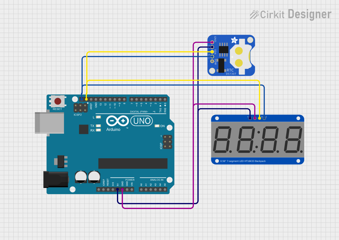
Interfacing with a Microcontroller

  1. Power Connections: Connect the VCC pin to the 5V output on your microcontroller and the GND pin to a ground pin.
  2. I2C Connections: Connect the SDA and SCL pins to the corresponding I2C pins on your microcontroller.
  3. Address Selection: If using multiple displays, solder the address jumpers on the back of the PCB to assign unique I2C addresses.

Programming the Display

To control the display with an Arduino UNO, you will need to use the Adafruit LED Backpack library. Install the library through the Arduino Library Manager or download it from the Adafruit GitHub repository.

Sample Arduino Code

#include <Wire.h>
#include <Adafruit_GFX.h>
#include <Adafruit_LEDBackpack.h>

Adafruit_7segment matrix = Adafruit_7segment();

void setup() {
  matrix.begin(0x70); // Initialize the display with its I2C address
}

void loop() {
  matrix.print(1234); // Display the number 1234
  matrix.writeDisplay(); // Refresh the display with new data
  delay(5000); // Wait for 5 seconds

  // Display a hexadecimal number
  matrix.print(0xBEEF, HEX);
  matrix.writeDisplay();
  delay(5000);
}

Best Practices

  • Always ensure that the power supply voltage and current ratings are within the specified range to prevent damage.
  • Use pull-up resistors on the I2C data lines if your microcontroller does not have built-in pull-ups.
  • Avoid exposing the display to moisture or extreme temperatures.

Troubleshooting and FAQs

Common Issues

  • Display Not Lighting Up: Check the power connections and ensure the I2C address is correctly set.
  • Garbled Output: Ensure there are no conflicts with other I2C devices and that the library is correctly installed.
  • Dim Display: Verify that the power supply is providing sufficient voltage and current.

FAQs

Q: Can I use this display with a 3.3V system? A: While the display operates at 4.5V - 5.5V, many 3.3V microcontrollers can interface with it without level shifting. However, the brightness may be reduced.

Q: How do I change the I2C address? A: Solder the address jumpers on the back of the display to configure the address between 0x70 and 0x77.

Q: Can the display show characters other than numbers? A: The display is primarily designed for numeric output, but it can show a limited set of characters and symbols.

For further assistance, consult the Adafruit support forums or the product's FAQ page.