Cirkit Designer Logo
Cirkit Designer
Your all-in-one circuit design IDE
Home / 
Component Documentation

How to Use IP5306: Examples, Pinouts, and Specs

Image of IP5306
Cirkit Designer LogoDesign with IP5306 in Cirkit Designer

Introduction

The IP5306 is a highly integrated power management IC developed by Injoinic Technology Co., Ltd. It is specifically designed for lithium-ion battery charging and protection. This versatile component combines a battery charger, a load switch, and a battery protection circuit into a single package, making it ideal for portable electronic devices.

Explore Projects Built with IP5306

Use Cirkit Designer to design, explore, and prototype these projects online. Some projects support real-time simulation. Click "Open Project" to start designing instantly!
Battery-Powered Raspberry Pi Pico GPS Tracker with Sensor Integration
Image of Copy of CanSet v1: A project utilizing IP5306 in a practical application
This circuit is a data acquisition and communication system powered by a LiPoly battery and managed by a Raspberry Pi Pico. It includes sensors (BMP280, MPU9250) for environmental data, a GPS module for location tracking, an SD card for data storage, and a WLR089-CanSAT for wireless communication. The TP4056 module handles battery charging, and a toggle switch controls power distribution.
Cirkit Designer LogoOpen Project in Cirkit Designer
Arduino Mega 2560 Based Security System with Fingerprint Authentication and SMS Alerts
Image of Door security system: A project utilizing IP5306 in a practical application
This circuit features an Arduino Mega 2560 microcontroller interfaced with a SIM800L GSM module, two fingerprint scanners, an I2C LCD display, an IR sensor, and a piezo buzzer. Power management is handled by a PowerBoost 1000 Basic Pad USB, a TP4056 charging module, and a Li-ion 18650 battery, with an option to use a Mini AC-DC 110V-230V to 5V 700mA module for direct power supply. The primary functionality appears to be a security system with GSM communication capabilities, biometric access control, and visual/audible feedback.
Cirkit Designer LogoOpen Project in Cirkit Designer
ESP32-Based Battery-Powered Multi-Sensor System
Image of Dive sense: A project utilizing IP5306 in a practical application
This circuit consists of a TP4056 module connected to a 3.7V LiPo battery, providing a charging interface for the battery. The TP4056 manages the charging process by connecting its B+ and B- pins to the battery's positive and ground terminals, respectively.
Cirkit Designer LogoOpen Project in Cirkit Designer
Battery-Powered Audio Playback and Amplification System
Image of recorder: A project utilizing IP5306 in a practical application
This circuit is designed to charge 18650 lithium-ion batteries using a TP4056 charger module, and then boost the voltage using an XL 6009 Boost Module. The boosted voltage is regulated by a 7805 voltage regulator to provide a stable 5V output, which powers an ISD1820 voice recording and playback module. The audio signal from the ISD1820 is then amplified by an LM386 audio amplifier module and output through a loudspeaker.
Cirkit Designer LogoOpen Project in Cirkit Designer

Explore Projects Built with IP5306

Use Cirkit Designer to design, explore, and prototype these projects online. Some projects support real-time simulation. Click "Open Project" to start designing instantly!
Image of Copy of CanSet v1: A project utilizing IP5306 in a practical application
Battery-Powered Raspberry Pi Pico GPS Tracker with Sensor Integration
This circuit is a data acquisition and communication system powered by a LiPoly battery and managed by a Raspberry Pi Pico. It includes sensors (BMP280, MPU9250) for environmental data, a GPS module for location tracking, an SD card for data storage, and a WLR089-CanSAT for wireless communication. The TP4056 module handles battery charging, and a toggle switch controls power distribution.
Cirkit Designer LogoOpen Project in Cirkit Designer
Image of Door security system: A project utilizing IP5306 in a practical application
Arduino Mega 2560 Based Security System with Fingerprint Authentication and SMS Alerts
This circuit features an Arduino Mega 2560 microcontroller interfaced with a SIM800L GSM module, two fingerprint scanners, an I2C LCD display, an IR sensor, and a piezo buzzer. Power management is handled by a PowerBoost 1000 Basic Pad USB, a TP4056 charging module, and a Li-ion 18650 battery, with an option to use a Mini AC-DC 110V-230V to 5V 700mA module for direct power supply. The primary functionality appears to be a security system with GSM communication capabilities, biometric access control, and visual/audible feedback.
Cirkit Designer LogoOpen Project in Cirkit Designer
Image of Dive sense: A project utilizing IP5306 in a practical application
ESP32-Based Battery-Powered Multi-Sensor System
This circuit consists of a TP4056 module connected to a 3.7V LiPo battery, providing a charging interface for the battery. The TP4056 manages the charging process by connecting its B+ and B- pins to the battery's positive and ground terminals, respectively.
Cirkit Designer LogoOpen Project in Cirkit Designer
Image of recorder: A project utilizing IP5306 in a practical application
Battery-Powered Audio Playback and Amplification System
This circuit is designed to charge 18650 lithium-ion batteries using a TP4056 charger module, and then boost the voltage using an XL 6009 Boost Module. The boosted voltage is regulated by a 7805 voltage regulator to provide a stable 5V output, which powers an ISD1820 voice recording and playback module. The audio signal from the ISD1820 is then amplified by an LM386 audio amplifier module and output through a loudspeaker.
Cirkit Designer LogoOpen Project in Cirkit Designer

Common Applications

  • Power banks
  • Portable speakers
  • Wearable devices
  • IoT devices
  • Handheld gadgets

The IP5306 simplifies the design of battery-powered systems by providing efficient charging, overcurrent protection, and seamless power delivery.


Technical Specifications

Key Technical Details

Parameter Value
Input Voltage Range 4.5V to 6.0V
Battery Voltage Range 2.9V to 4.2V
Charging Current Up to 2.4A
Output Voltage 5V (Boost Mode)
Output Current Up to 2.1A
Efficiency (Boost Mode) Up to 92%
Quiescent Current < 50µA
Protection Features Overcharge, Overdischarge, Overcurrent,
Short Circuit Protection
Package Type ESOP-8

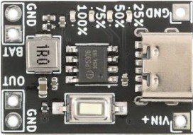
Pin Configuration and Descriptions

The IP5306 is available in an ESOP-8 package. Below is the pinout and description:

Pin No. Pin Name Description
1 VIN Input voltage pin for charging (4.5V to 6.0V). Connect to a USB or DC input.
2 GND Ground pin. Connect to the system ground.
3 BAT Battery connection pin. Connect to the positive terminal of the lithium-ion
battery.
4 SW Switching node for the boost converter. Connect to an inductor.
5 VOUT Output voltage pin (5V in boost mode). Connect to the load.
6 EN Enable pin. High to enable the boost converter, low to disable.
7 STAT Status indicator pin. Used to indicate charging or fault conditions.
8 NC No connection. Leave this pin unconnected.

Usage Instructions

How to Use the IP5306 in a Circuit

  1. Power Input: Connect the VIN pin to a 5V power source, such as a USB port or DC adapter.
  2. Battery Connection: Attach the positive terminal of the lithium-ion battery to the BAT pin and the negative terminal to GND.
  3. Output Connection: Connect the load to the VOUT pin. Ensure the load does not exceed the maximum output current of 2.1A.
  4. Inductor Selection: Use an appropriate inductor (e.g., 2.2µH to 4.7µH) for the boost converter. Connect it between the SW pin and VOUT.
  5. Enable Control: Use the EN pin to enable or disable the boost converter. Pull the pin high to enable and low to disable.
  6. Status Monitoring: Use the STAT pin to monitor the charging status or detect faults.

Important Considerations

  • Thermal Management: Ensure proper heat dissipation by using a PCB with adequate thermal vias and copper planes.
  • Input Voltage: Do not exceed the maximum input voltage of 6.0V to avoid damaging the IC.
  • Battery Protection: The IP5306 includes built-in overcharge and overdischarge protection, but ensure the battery used is compatible with these features.
  • Capacitor Selection: Use low-ESR capacitors (e.g., 10µF ceramic capacitors) at the input and output for stable operation.

Example: Using IP5306 with Arduino UNO

The IP5306 can be used to power an Arduino UNO via its 5V output. Below is an example of how to monitor the charging status using the STAT pin:

// Arduino code to monitor the IP5306 charging status
const int statPin = 2; // Connect the STAT pin of IP5306 to Arduino pin 2

void setup() {
  pinMode(statPin, INPUT); // Set STAT pin as input
  Serial.begin(9600);      // Initialize serial communication
}

void loop() {
  int stat = digitalRead(statPin); // Read the STAT pin
  if (stat == HIGH) {
    Serial.println("Charging in progress or fault detected.");
  } else {
    Serial.println("Charging complete or no fault.");
  }
  delay(1000); // Wait for 1 second before checking again
}

Troubleshooting and FAQs

Common Issues and Solutions

Issue Possible Cause Solution
No output voltage on VOUT Boost converter not enabled Ensure the EN pin is pulled high.
Battery not charging Input voltage too low Verify that VIN is between 4.5V-6.0V.
Overheating Excessive load or poor thermal design Reduce load or improve PCB heat dissipation.
STAT pin always HIGH Fault condition or no battery connected Check battery connection and status.

FAQs

  1. Can the IP5306 charge multiple batteries in series?
    No, the IP5306 is designed for single-cell lithium-ion batteries only.

  2. What happens if the input voltage exceeds 6.0V?
    Exceeding 6.0V can damage the IC. Always use a regulated power source within the specified range.

  3. Can I use the IP5306 without a battery?
    Yes, but the output may not be stable under varying load conditions. A battery is recommended for optimal performance.

  4. How do I know if the battery is fully charged?
    The STAT pin will indicate the charging status. When charging is complete, the pin will typically go low.

By following this documentation, users can effectively integrate the IP5306 into their designs for reliable power management.