How to Use Arduino Mega 2560: Examples, Pinouts, and Specs
Introduction
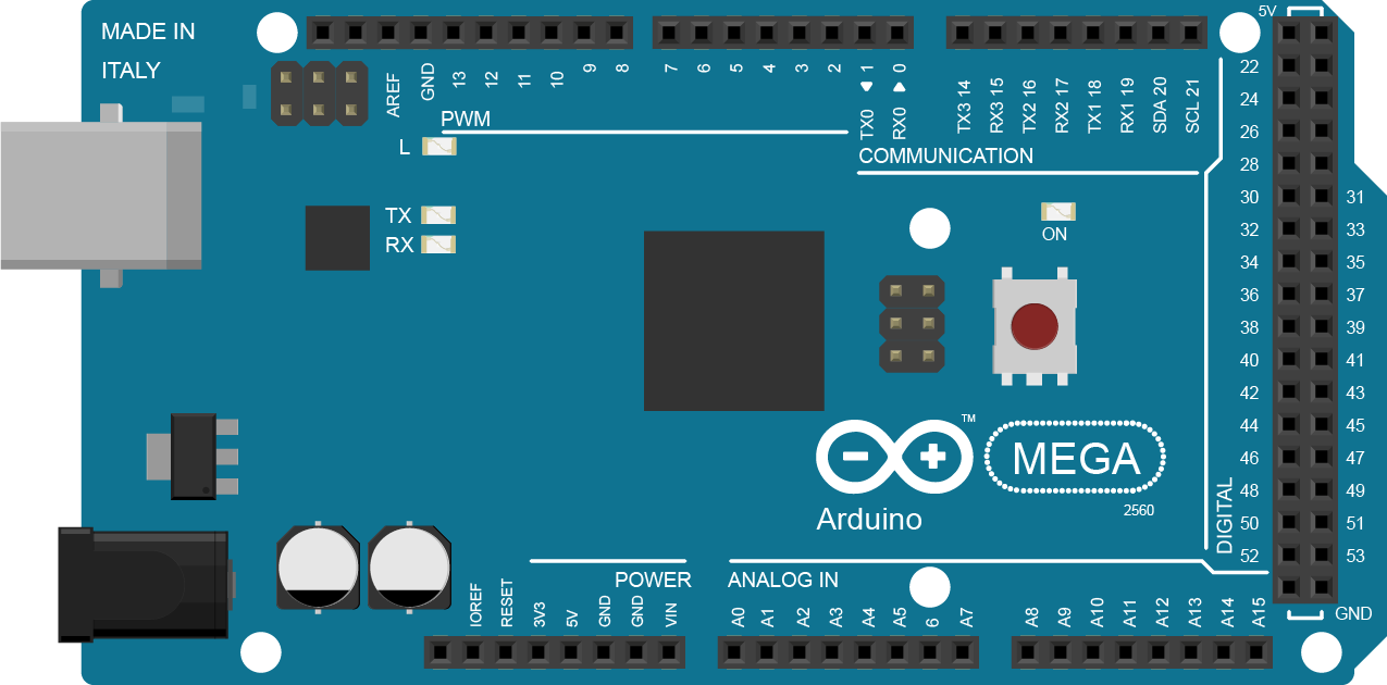
The Arduino Mega 2560 is a versatile microcontroller board based on the ATmega2560 chip. It is an integral part of the Arduino family, designed to provide a platform for building digital devices and interactive objects that can sense and control the physical world. With its extensive array of input/output (I/O) pins, it is particularly suited for projects that require multiple sensors, actuators, or a significant amount of control logic.
Explore Projects Built with Arduino Mega 2560
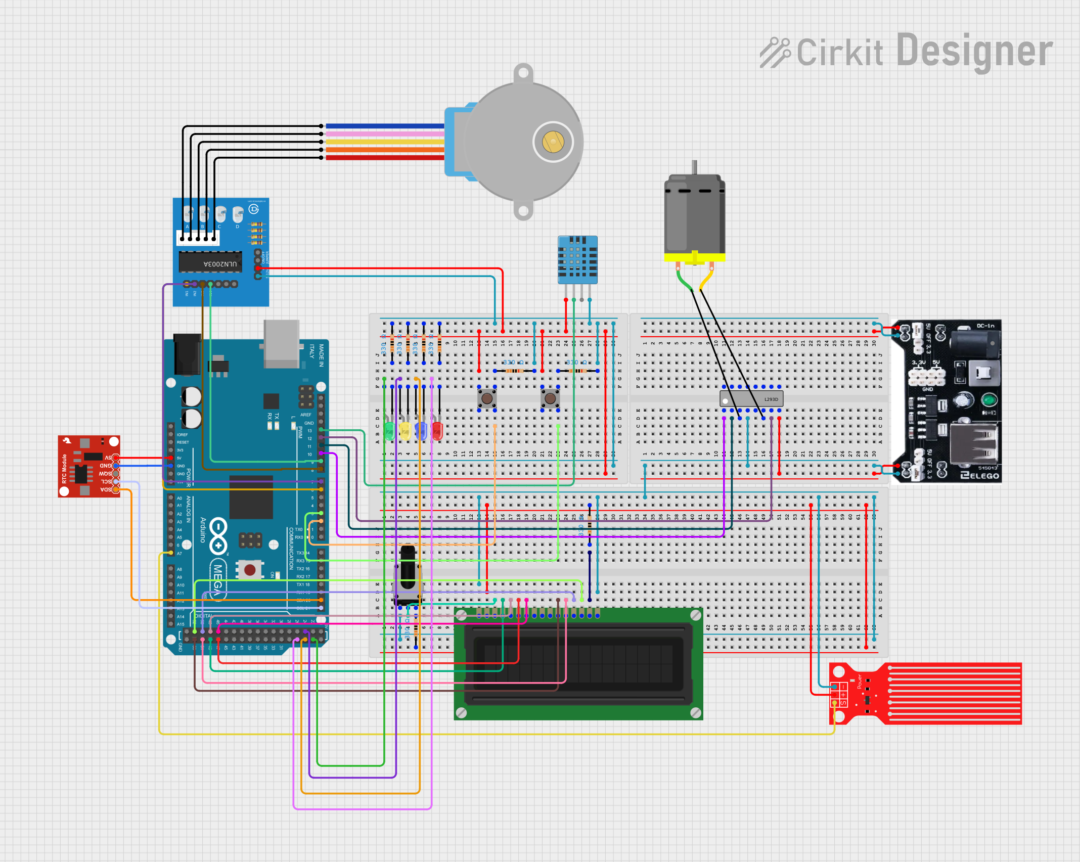
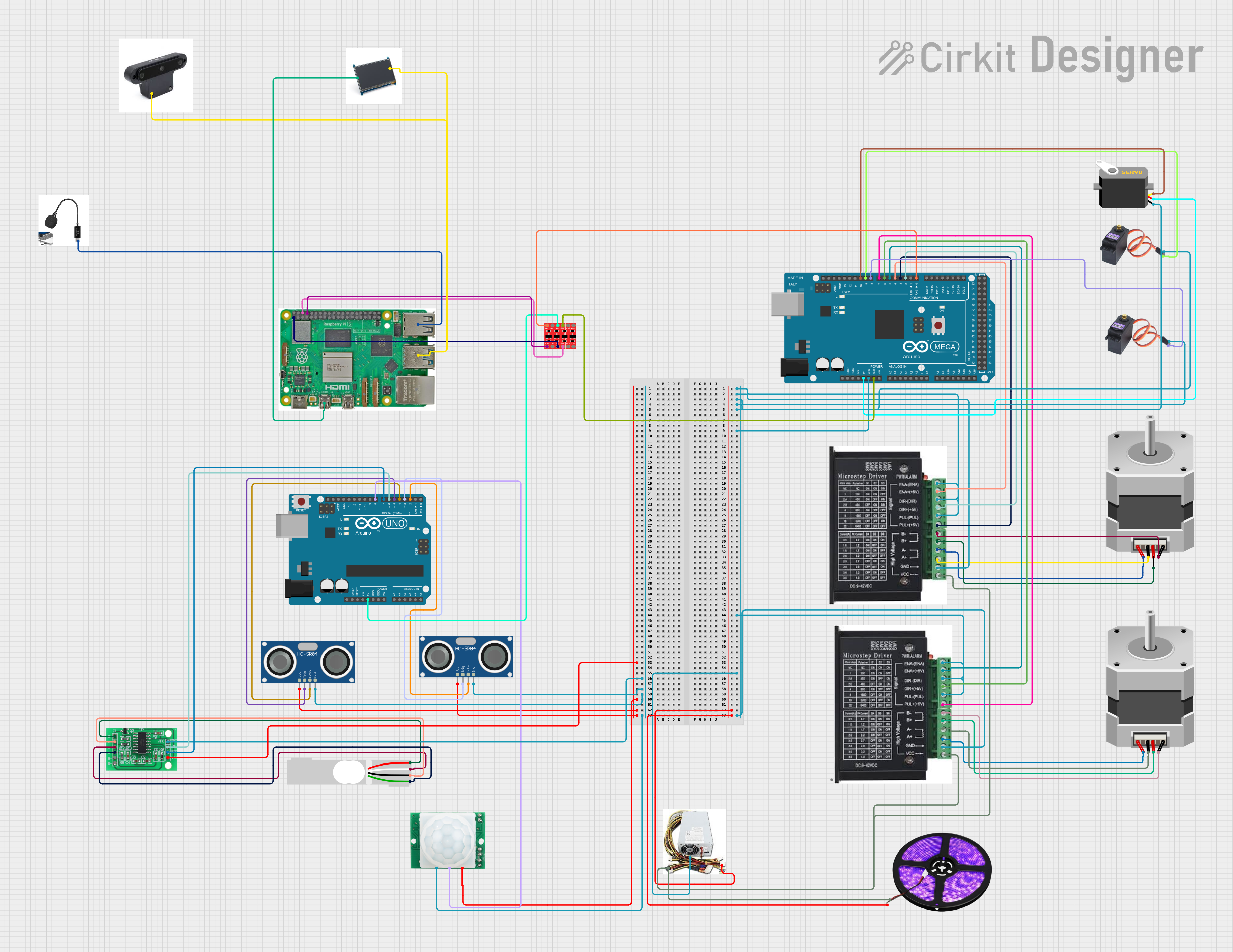
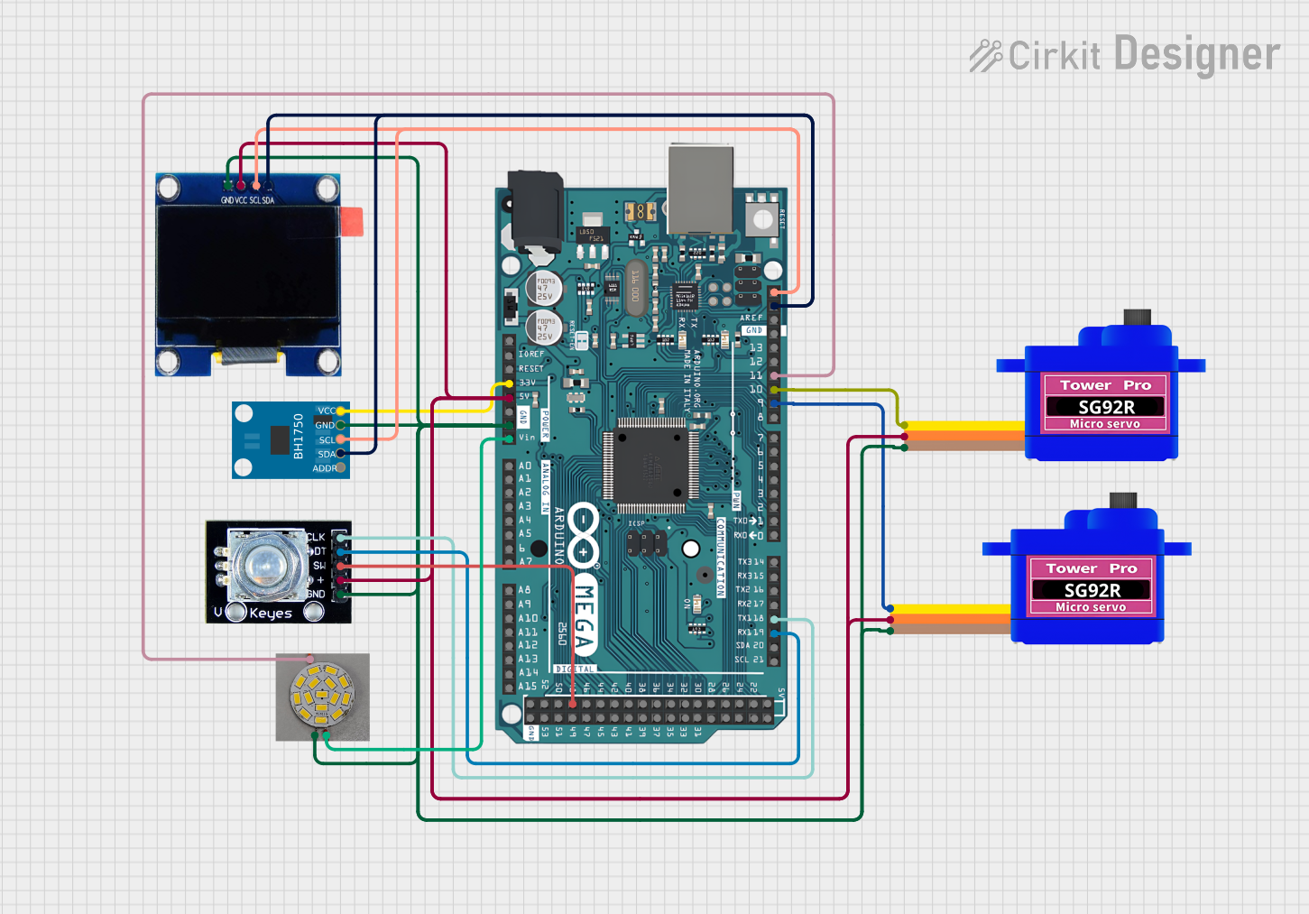
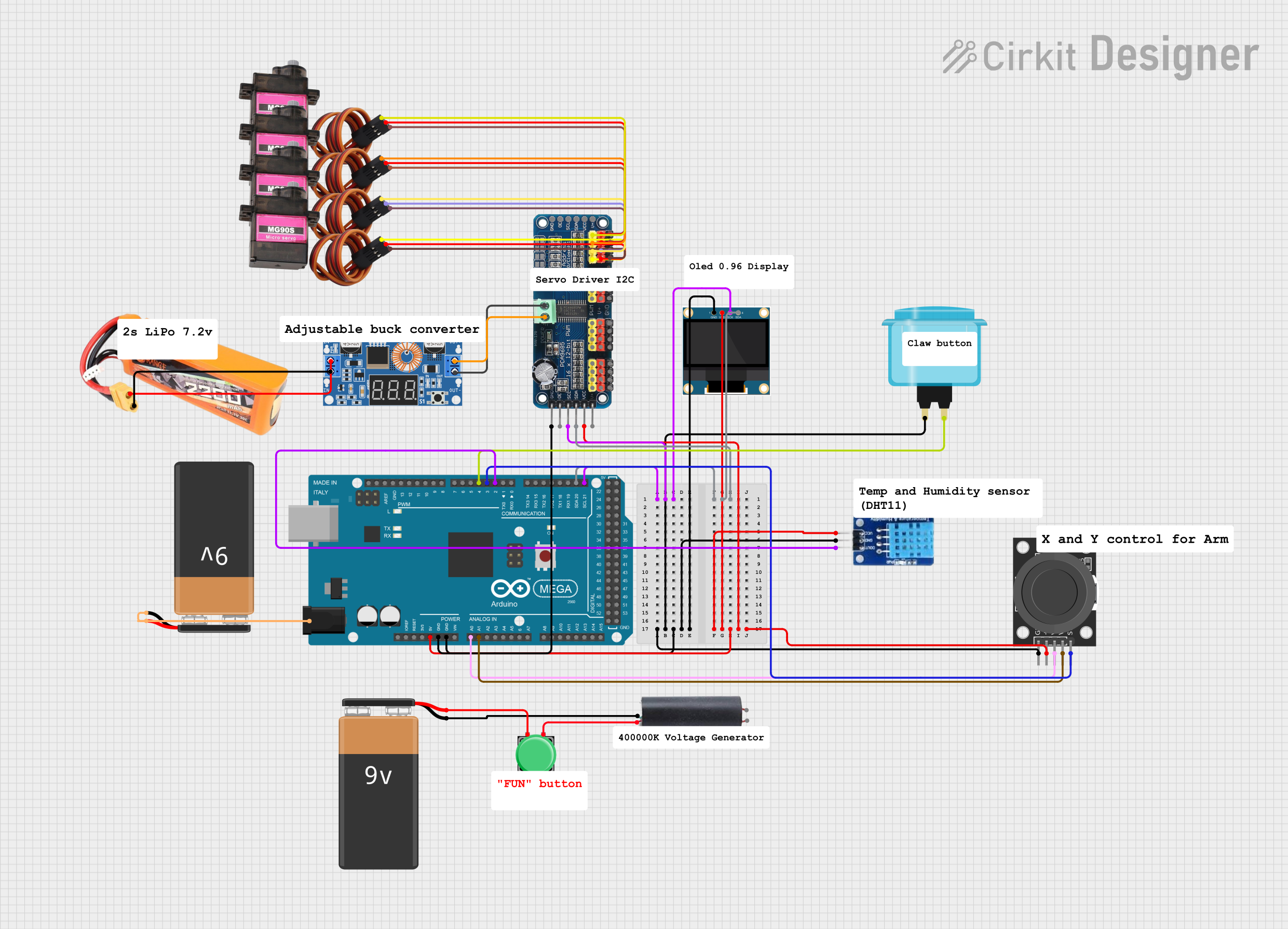
Explore Projects Built with Arduino Mega 2560
Common Applications and Use Cases
- Robotics
- Home automation systems
- Complex LED light displays
- Multi-axis CNC machines
- Data logging and sensor networks
Technical Specifications
Key Technical Details
- Microcontroller: ATmega2560
- Operating Voltage: 5V
- Input Voltage (recommended): 7-12V
- Input Voltage (limits): 6-20V
- Digital I/O Pins: 54 (of which 15 provide PWM output)
- Analog Input Pins: 16
- DC Current per I/O Pin: 20 mA
- DC Current for 3.3V Pin: 50 mA
- Flash Memory: 256 KB of which 8 KB used by bootloader
- SRAM: 8 KB
- EEPROM: 4 KB
- Clock Speed: 16 MHz
- LED_BUILTIN: Pin 13
Pin Configuration and Descriptions
| Pin Number | Function | Description |
|---|---|---|
| 1-54 | Digital I/O | Digital pins which can be used as input or output |
| 1-15 | PWM | Pins that support Pulse Width Modulation |
| A0-A15 | Analog Input | Analog pins which can be used to read analog voltages |
| 5V | Power Output | Provides 5V output to external components |
| 3.3V | Power Output | Provides 3.3V output to external components |
| GND | Ground | Common ground for circuits |
| RST | Reset | Resets the microcontroller |
| TX0, RX0 | Serial 0 | Used for serial communication |
| SDA, SCL | I2C | Used for I2C communication |
| AREF | Analog Reference | Used for reference voltage for the analog inputs |
| 3.3V, 5V, GND | Power Rails | Power supply pins for the board and external components |
Usage Instructions
How to Use the Arduino Mega 2560 in a Circuit
Powering the Board:
- Connect a 7-12V power supply to the VIN pin or use the USB connection.
- Ensure that the power supply is within the recommended limits to prevent damage.
Connecting I/O Devices:
- Connect sensors to the analog pins for analog input.
- Connect actuators or other peripherals to the digital pins.
- Use PWM pins for devices that require variable power, like motors.
Programming the Board:
- Connect the board to a computer using a USB cable.
- Use the Arduino IDE to write and upload sketches to the board.
Important Considerations and Best Practices
- Always disconnect the board from the power source before making or altering connections.
- Ensure that the current draw from each I/O pin does not exceed 20 mA.
- Use external power sources when connecting devices that draw more current than the board can provide.
- Avoid exposing the board to extreme temperatures, moisture, or dust.
Troubleshooting and FAQs
Common Issues
Board not recognized by computer:
- Check the USB cable and connections.
- Ensure the correct drivers are installed.
Sketch not uploading:
- Verify the correct board and port are selected in the Arduino IDE.
- Check for errors in the code and ensure the correct bootloader is used.
Unexpected behavior in circuits:
- Double-check wiring and connections.
- Ensure power supply is stable and within recommended limits.
Solutions and Tips for Troubleshooting
- Use the onboard LED (pin 13) to test basic sketches and ensure the board is functioning.
- Utilize the Arduino IDE's Serial Monitor to debug and monitor data from the board.
- Consult the Arduino forums and community for support on specific issues.
Example Code for Arduino Mega 2560
Here is a simple example of blinking the onboard LED using the Arduino Mega 2560:
// Define the LED pin
const int ledPin = 13;

// The setup function runs once when you press reset or power the board
void setup() {
  // Initialize the digital pin as an output.
  pinMode(ledPin, OUTPUT);
}

// The loop function runs over and over again forever
void loop() {
  digitalWrite(ledPin, HIGH);   // Turn the LED on
  delay(1000);                  // Wait for a second
  digitalWrite(ledPin, LOW);    // Turn the LED off
  delay(1000);                  // Wait for a second
}
Remember to select "Arduino Mega or Mega 2560" as the board within the Arduino IDE before uploading the code.