How to Use HuskyLens K210 AI Camera: Examples, Pinouts, and Specs
Introduction
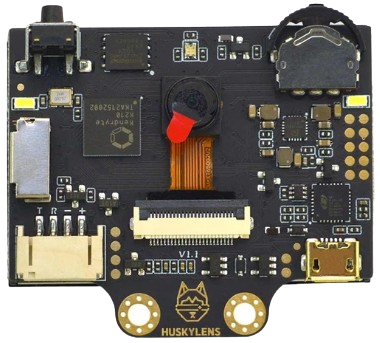
The HuskyLens K210 AI Camera is a smart AI-powered camera module that leverages the K210 chip for advanced image recognition and processing. It is designed to simplify AI-based tasks such as object tracking, face recognition, gesture detection, and more. With its user-friendly interface and built-in algorithms, the HuskyLens is an excellent choice for hobbyists, educators, and developers looking to integrate AI capabilities into their projects.
Explore Projects Built with HuskyLens K210 AI Camera
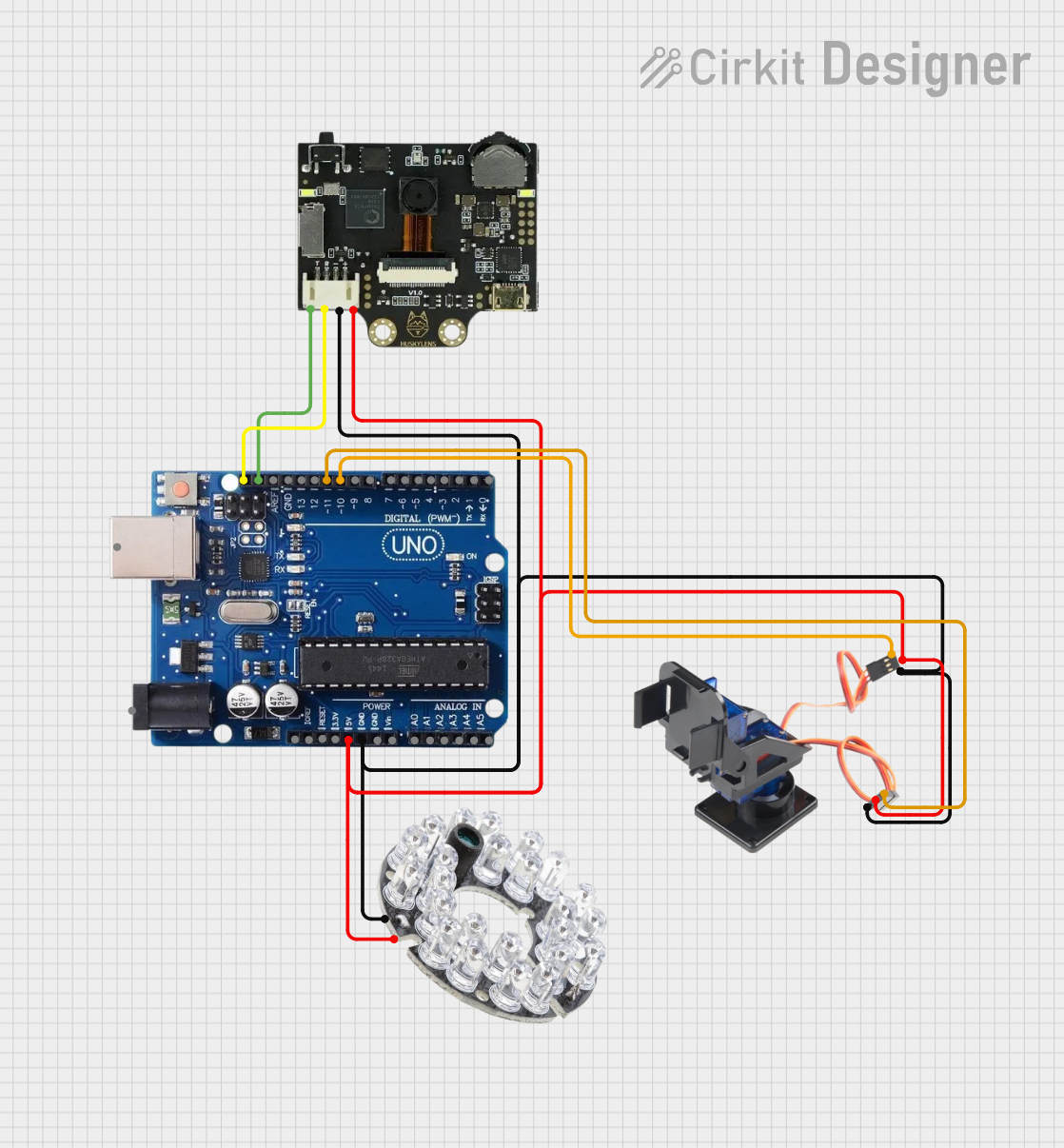
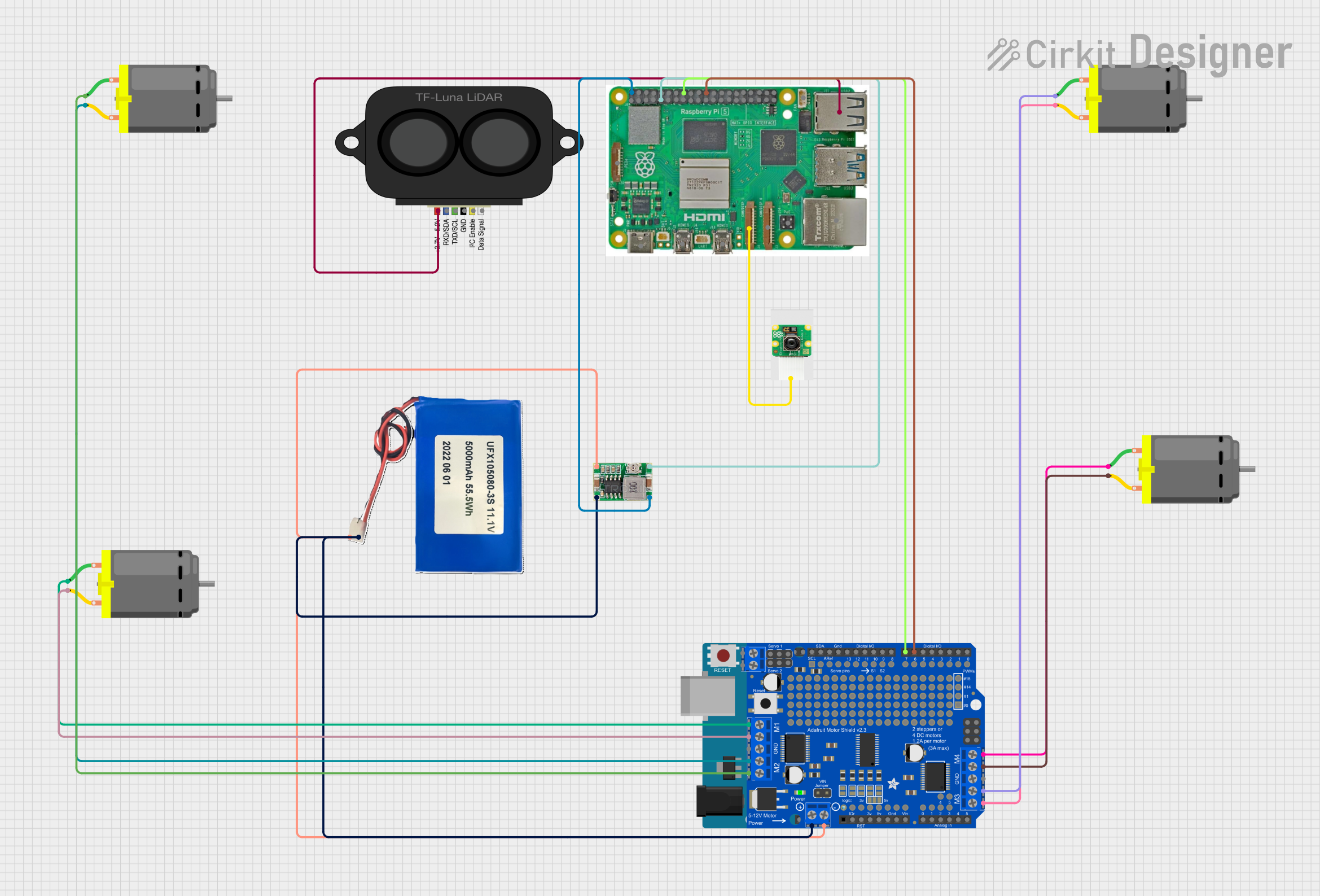
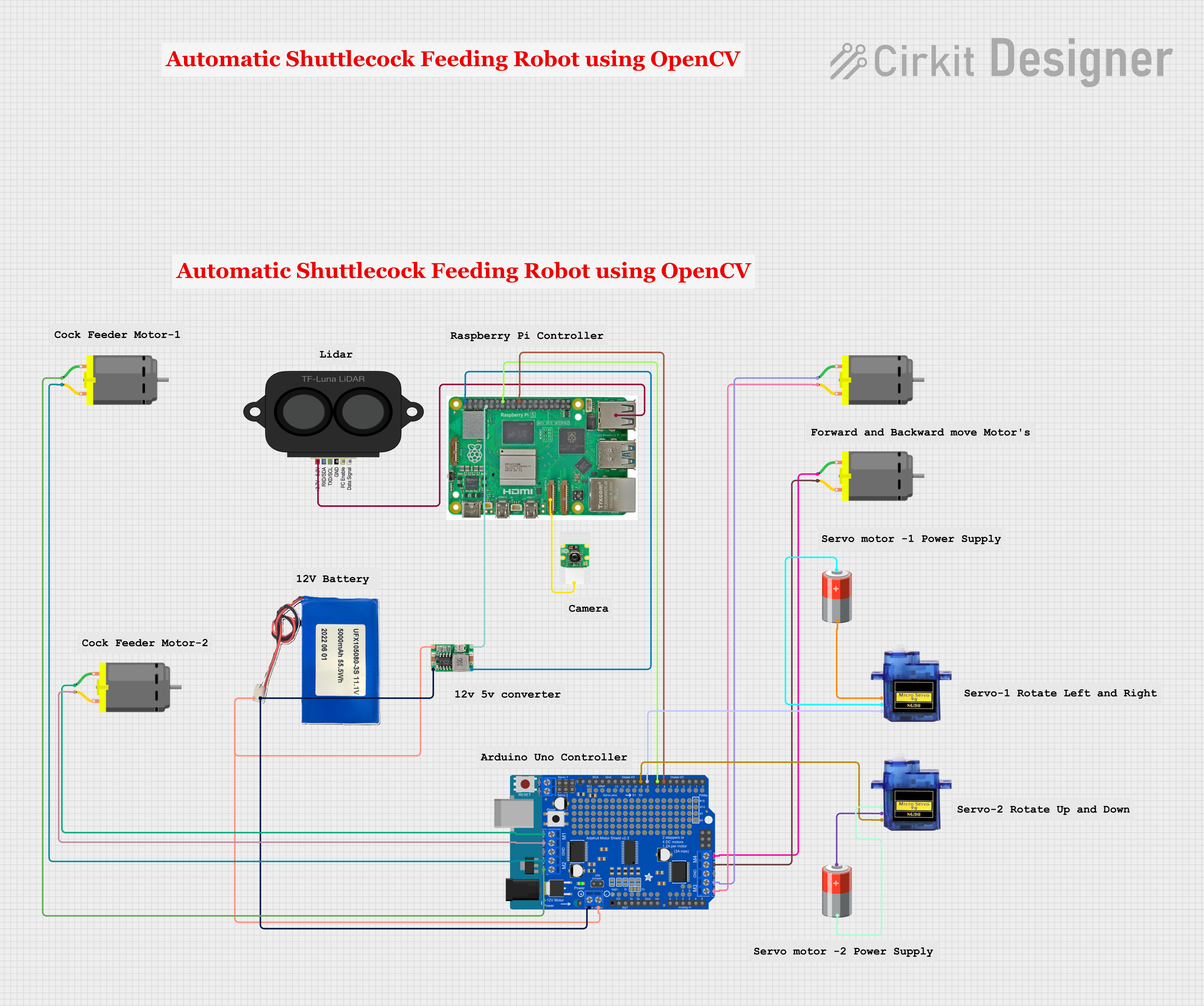

Explore Projects Built with HuskyLens K210 AI Camera
Common Applications and Use Cases
- Object tracking for robotics and automation
- Face recognition for security systems
- Gesture detection for interactive devices
- Line following for autonomous vehicles
- Barcode and QR code scanning
- Educational projects and AI learning
Technical Specifications
Key Technical Details
- Processor: Kendryte K210 dual-core RISC-V 64-bit processor
- Image Sensor: OV2640 (2MP) or OV5640 (5MP) camera module
- Display: 2-inch IPS screen for real-time feedback
- Communication Interfaces: UART, I2C
- Input Voltage: 3.3V to 5V
- Power Consumption: ~200mA at 5V
- Storage: Built-in flash memory for saving models and settings
- Dimensions: 52mm x 44mm x 20mm
- Weight: ~30g
Pin Configuration and Descriptions
The HuskyLens K210 AI Camera has a 4-pin interface for communication and power. Below is the pin configuration:
| Pin | Name | Description |
|---|---|---|
| 1 | VCC | Power input (3.3V to 5V) |
| 2 | GND | Ground |
| 3 | TX | UART Transmit (data output) |
| 4 | RX | UART Receive (data input) |
For I2C communication, the HuskyLens uses the following pins:
| Pin | Name | Description |
|---|---|---|
| 3 | SCL | I2C Clock Line |
| 4 | SDA | I2C Data Line |
Usage Instructions
How to Use the Component in a Circuit
- Power the HuskyLens: Connect the VCC pin to a 3.3V or 5V power source and the GND pin to ground.
- Choose a Communication Protocol: Decide whether to use UART or I2C for communication with your microcontroller or development board.
- Connect to a Microcontroller:
- For UART: Connect the TX pin of the HuskyLens to the RX pin of the microcontroller, and the RX pin of the HuskyLens to the TX pin of the microcontroller.
- For I2C: Connect the SCL and SDA pins to the corresponding I2C pins on the microcontroller.
- Initialize the HuskyLens: Use the provided libraries or commands to initialize the camera and configure its settings.
- Select a Function: Use the onboard buttons or serial commands to select the desired AI function (e.g., object tracking, face recognition).
- Train the Model: Point the camera at the object or face you want to recognize and press the "Learn" button to train the model.
- Integrate with Your Project: Use the output data from the HuskyLens to control other components or systems in your project.
Important Considerations and Best Practices
- Ensure the power supply is stable and within the specified voltage range (3.3V to 5V).
- Use the official HuskyLens library for seamless integration with Arduino or other platforms.
- Avoid exposing the camera to direct sunlight or reflective surfaces, as this may affect recognition accuracy.
- Regularly update the firmware to access the latest features and improvements.
Example Code for Arduino UNO
Below is an example of how to use the HuskyLens with an Arduino UNO via UART:
#include <SoftwareSerial.h>

// Define the RX and TX pins for SoftwareSerial
SoftwareSerial huskySerial(2, 3); // RX = Pin 2, TX = Pin 3

void setup() {
  Serial.begin(9600); // Initialize Serial Monitor
  huskySerial.begin(9600); // Initialize HuskyLens communication

  // Send initialization command to HuskyLens
  Serial.println("Initializing HuskyLens...");
  huskySerial.write(0x55); // Send a sample command to wake up the device
}

void loop() {
  // Check if data is available from HuskyLens
  if (huskySerial.available()) {
    String data = "";
    while (huskySerial.available()) {
      char c = huskySerial.read(); // Read data from HuskyLens
      data += c;
    }
    Serial.println("Data from HuskyLens: " + data); // Print data to Serial Monitor
  }

  delay(100); // Small delay to avoid flooding the Serial Monitor
}
Troubleshooting and FAQs
Common Issues and Solutions
HuskyLens Not Powering On
- Cause: Insufficient or unstable power supply.
- Solution: Ensure the power source provides 3.3V to 5V and can supply at least 200mA.
No Data Received from HuskyLens
- Cause: Incorrect wiring or baud rate mismatch.
- Solution: Double-check the TX and RX connections. Ensure the baud rate in your code matches the HuskyLens default (9600 bps).
Recognition Accuracy is Low
- Cause: Poor lighting or complex backgrounds.
- Solution: Improve lighting conditions and ensure the object or face is clearly visible.
Unable to Train the Model
- Cause: Incorrect button usage or unstable object position.
- Solution: Hold the object steady and press the "Learn" button firmly. Ensure the object is within the camera's field of view.
FAQs
Q: Can the HuskyLens be used with Raspberry Pi?
A: Yes, the HuskyLens supports UART and I2C communication, making it compatible with Raspberry Pi. Use the appropriate libraries for integration.
Q: How many objects can the HuskyLens recognize simultaneously?
A: The HuskyLens can recognize multiple objects simultaneously, depending on the selected function and available memory.
Q: Is the firmware upgradable?
A: Yes, the firmware can be updated using the official HuskyLens software and a USB connection.
Q: Can I use the HuskyLens without a microcontroller?
A: Yes, the HuskyLens can operate independently for basic tasks using its onboard buttons and display.
By following this documentation, you can effectively integrate the HuskyLens K210 AI Camera into your projects and unlock its full potential for AI-based applications.