Cirkit Designer Logo
Cirkit Designer
Your all-in-one circuit design IDE
Home / 
Component Documentation

How to Use Adafruit 1.2 Inch 8x8 LED Matrix Backpack White: Examples, Pinouts, and Specs

Image of Adafruit 1.2 Inch 8x8 LED Matrix Backpack White
Cirkit Designer LogoDesign with Adafruit 1.2 Inch 8x8 LED Matrix Backpack White in Cirkit Designer

Introduction

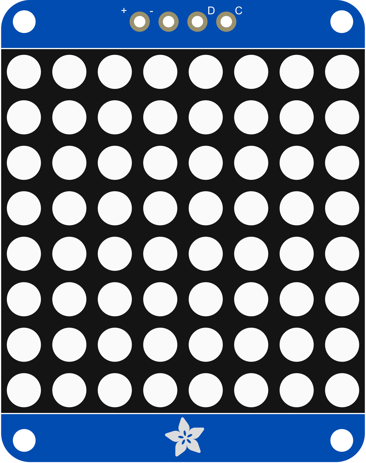
The Adafruit 1.2 Inch 8x8 LED Matrix Backpack is a compact and easy-to-use hardware module that simplifies the process of controlling an 8x8 grid of white LEDs. This component is ideal for creating displays for characters, symbols, and simple graphics in various electronics projects. Common applications include wearable electronics, message boards, and educational tools for teaching programming and electronics.

Explore Projects Built with Adafruit 1.2 Inch 8x8 LED Matrix Backpack White

Use Cirkit Designer to design, explore, and prototype these projects online. Some projects support real-time simulation. Click "Open Project" to start designing instantly!
Arduino UNO WiFi-Controlled LED Matrix Display
Image of SMD2121 Led screen - r4: A project utilizing Adafruit 1.2 Inch 8x8 LED Matrix Backpack White in a practical application
This circuit consists of an Arduino UNO R4 WiFi microcontroller connected to a 64x32 LED matrix. The Arduino controls the LED matrix by sending signals to various pins to display different colors and patterns, as defined in the embedded code.
Cirkit Designer LogoOpen Project in Cirkit Designer
Arduino-Controlled RGB LED Matrix Display
Image of SMD2121 Led screen: A project utilizing Adafruit 1.2 Inch 8x8 LED Matrix Backpack White in a practical application
This circuit connects an Arduino UNO R4 WiFi microcontroller to a 64x32 LED matrix display. The Arduino is configured to control the LED matrix, sending color data and control signals to display various colors across the matrix. The embedded code on the Arduino cycles through a range of colors, filling the entire LED matrix with each color in sequence.
Cirkit Designer LogoOpen Project in Cirkit Designer
ESP32-Controlled Dual 8x8 LED Matrix Display with NTP Time Synchronization
Image of time: A project utilizing Adafruit 1.2 Inch 8x8 LED Matrix Backpack White in a practical application
This circuit features an ESP32 microcontroller connected to two cascaded 8x8 LED matrix displays, powered by a 3.3V battery. The ESP32 drives the displays to show time and other information, with the code indicating functionality for connecting to WiFi, synchronizing time via NTP, and displaying data on the matrices using custom fonts. Additionally, there is a separate 3.3V battery powering a red LED, which appears to function as a simple indicator light.
Cirkit Designer LogoOpen Project in Cirkit Designer
ESP32-Controlled WS2812 LED Matrix Display with Resistor
Image of esp32 door sign project: A project utilizing Adafruit 1.2 Inch 8x8 LED Matrix Backpack White in a practical application
This circuit features an ESP32 microcontroller connected to a 32x8 WS2812 LED matrix. The ESP32 controls the LED matrix through a 220-ohm resistor connected to its D12 pin, providing data input to the matrix, while power and ground connections are shared between the ESP32 and the LED matrix.
Cirkit Designer LogoOpen Project in Cirkit Designer

Explore Projects Built with Adafruit 1.2 Inch 8x8 LED Matrix Backpack White

Use Cirkit Designer to design, explore, and prototype these projects online. Some projects support real-time simulation. Click "Open Project" to start designing instantly!
Image of SMD2121 Led screen - r4: A project utilizing Adafruit 1.2 Inch 8x8 LED Matrix Backpack White in a practical application
Arduino UNO WiFi-Controlled LED Matrix Display
This circuit consists of an Arduino UNO R4 WiFi microcontroller connected to a 64x32 LED matrix. The Arduino controls the LED matrix by sending signals to various pins to display different colors and patterns, as defined in the embedded code.
Cirkit Designer LogoOpen Project in Cirkit Designer
Image of SMD2121 Led screen: A project utilizing Adafruit 1.2 Inch 8x8 LED Matrix Backpack White in a practical application
Arduino-Controlled RGB LED Matrix Display
This circuit connects an Arduino UNO R4 WiFi microcontroller to a 64x32 LED matrix display. The Arduino is configured to control the LED matrix, sending color data and control signals to display various colors across the matrix. The embedded code on the Arduino cycles through a range of colors, filling the entire LED matrix with each color in sequence.
Cirkit Designer LogoOpen Project in Cirkit Designer
Image of time: A project utilizing Adafruit 1.2 Inch 8x8 LED Matrix Backpack White in a practical application
ESP32-Controlled Dual 8x8 LED Matrix Display with NTP Time Synchronization
This circuit features an ESP32 microcontroller connected to two cascaded 8x8 LED matrix displays, powered by a 3.3V battery. The ESP32 drives the displays to show time and other information, with the code indicating functionality for connecting to WiFi, synchronizing time via NTP, and displaying data on the matrices using custom fonts. Additionally, there is a separate 3.3V battery powering a red LED, which appears to function as a simple indicator light.
Cirkit Designer LogoOpen Project in Cirkit Designer
Image of esp32 door sign project: A project utilizing Adafruit 1.2 Inch 8x8 LED Matrix Backpack White in a practical application
ESP32-Controlled WS2812 LED Matrix Display with Resistor
This circuit features an ESP32 microcontroller connected to a 32x8 WS2812 LED matrix. The ESP32 controls the LED matrix through a 220-ohm resistor connected to its D12 pin, providing data input to the matrix, while power and ground connections are shared between the ESP32 and the LED matrix.
Cirkit Designer LogoOpen Project in Cirkit Designer

Technical Specifications

Key Technical Details

  • Display Color: White
  • Matrix Dimensions: 1.2 inches (8x8 grid)
  • Operating Voltage: 4.5V - 5.5V
  • Max Current (with all LEDs on): ~320 mA
  • Interface: I2C
  • I2C Addresses: 0x70 (default) - 0x77 (selectable with solder jumpers)

Pin Configuration and Descriptions

Pin Description
VCC Power supply (4.5V - 5.5V)
GND Ground connection
SDA I2C data line
SCL I2C clock line

Usage Instructions

Integrating with a Circuit

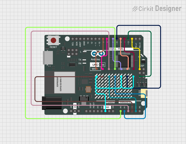
To use the Adafruit 1.2 Inch 8x8 LED Matrix Backpack in a circuit, follow these steps:

  1. Connect the VCC pin to a 5V power supply.
  2. Connect the GND pin to the ground of your power supply.
  3. Connect the SDA and SCL pins to the corresponding I2C data and clock lines on your microcontroller (e.g., Arduino UNO).

Important Considerations and Best Practices

  • Ensure that the power supply does not exceed 5.5V to prevent damage to the LED matrix.
  • If multiple LED matrix backpacks are used in a project, set unique I2C addresses for each using the solder jumpers on the back of the PCB.
  • Use pull-up resistors on the I2C lines if your microcontroller does not have built-in pull-ups.

Example Code for Arduino UNO

#include <Wire.h>
#include <Adafruit_GFX.h>
#include <Adafruit_LEDBackpack.h>

Adafruit_8x8matrix matrix = Adafruit_8x8matrix();

void setup() {
  matrix.begin(0x70); // Start the LED matrix with the I2C address
  matrix.setBrightness(10); // Set brightness level (0 is dim, 15 is bright)
}

void loop() {
  matrix.clear(); // Clear the matrix display
  matrix.drawPixel(4, 4, LED_ON); // Draw a single pixel
  matrix.writeDisplay(); // Write the changes to the display
  delay(500);
  matrix.clear(); // Clear the display again
  matrix.writeDisplay(); // Write the changes to the display
  delay(500);
}

This example initializes the LED matrix and blinks a single pixel on and off. Ensure you have installed the Adafruit_GFX and Adafruit_LEDBackpack libraries before uploading this code to your Arduino UNO.

Troubleshooting and FAQs

Common Issues

  • LEDs not lighting up: Check the power supply connections and ensure that the I2C address is correctly set.
  • Dim display: Increase the brightness using setBrightness() function or check the power supply voltage.
  • Garbled display: Ensure that there are no loose connections and that the I2C lines are connected properly.

Solutions and Tips for Troubleshooting

  • Double-check wiring, especially the I2C connections.
  • Use the i2cdetect tool or similar to confirm that the Arduino can communicate with the LED matrix.
  • If using multiple matrices, ensure that each has a unique I2C address.
  • Check the Adafruit forums and guides for additional support and resources.

FAQs

Q: Can I use this LED matrix with a 3.3V system?

A: While the matrix is rated for 4.5V - 5.5V, it may work at 3.3V with reduced brightness. However, this is not officially supported and may lead to unpredictable behavior.

Q: How do I change the I2C address?

A: Solder the address jumpers on the back of the PCB to configure the address between 0x70 and 0x77.

Q: Can I daisy-chain multiple matrices?

A: Yes, you can connect multiple matrices in series by connecting the SDA and SCL lines in parallel and providing each matrix with a unique I2C address.