How to Use SparkFun_Roshamglo: Examples, Pinouts, and Specs
Introduction
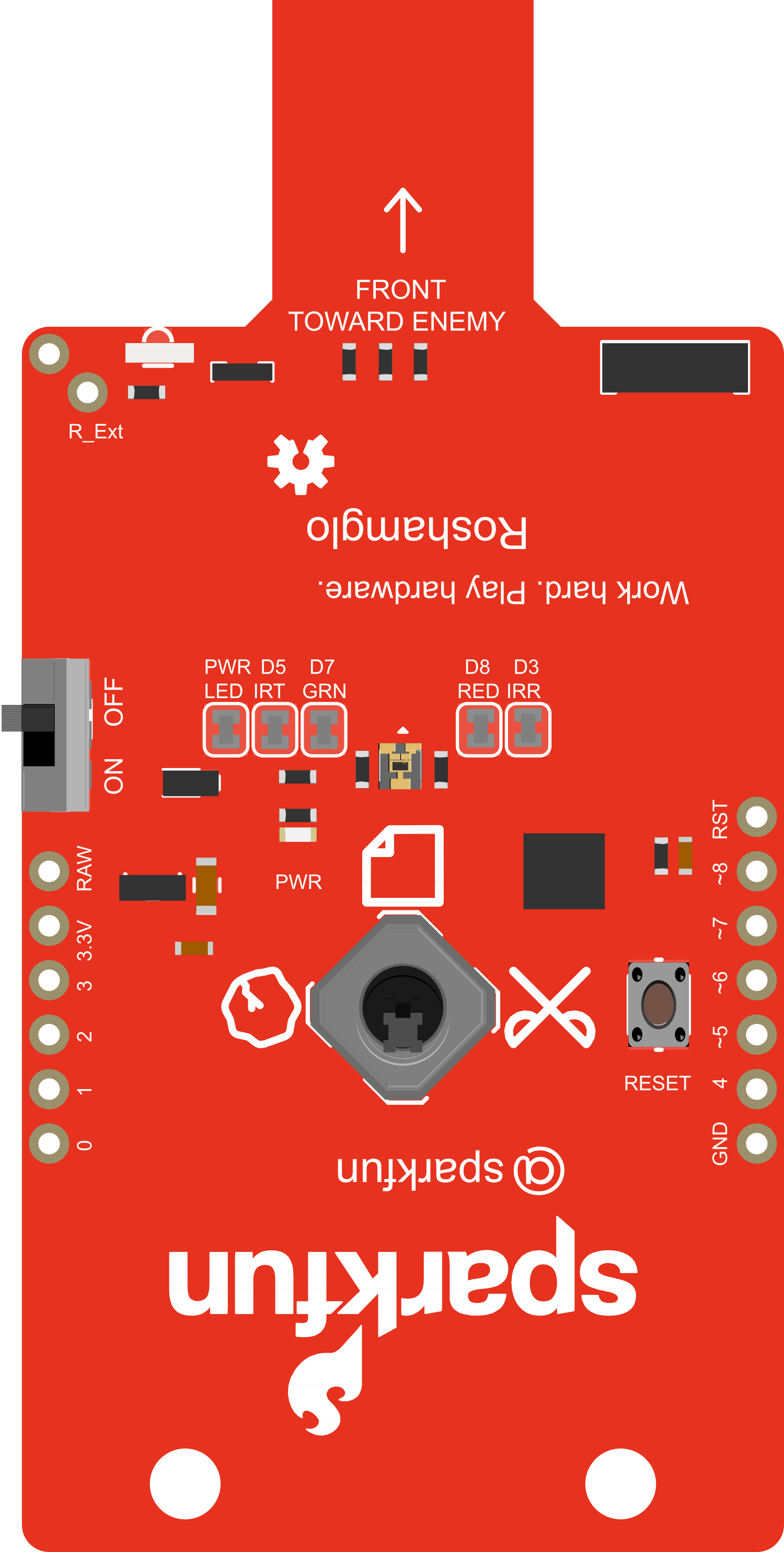
The SparkFun Roshamglo is an interactive badge that lets you play rock-paper-scissors, the classic hand game, with a modern twist. It is equipped with an ATtiny84 microcontroller, an LED matrix for displaying game symbols, and push buttons for player input. This badge is not only a fun gadget but also serves as a development platform compatible with the Arduino programming environment, making it a versatile tool for learning and prototyping.
Explore Projects Built with SparkFun_Roshamglo

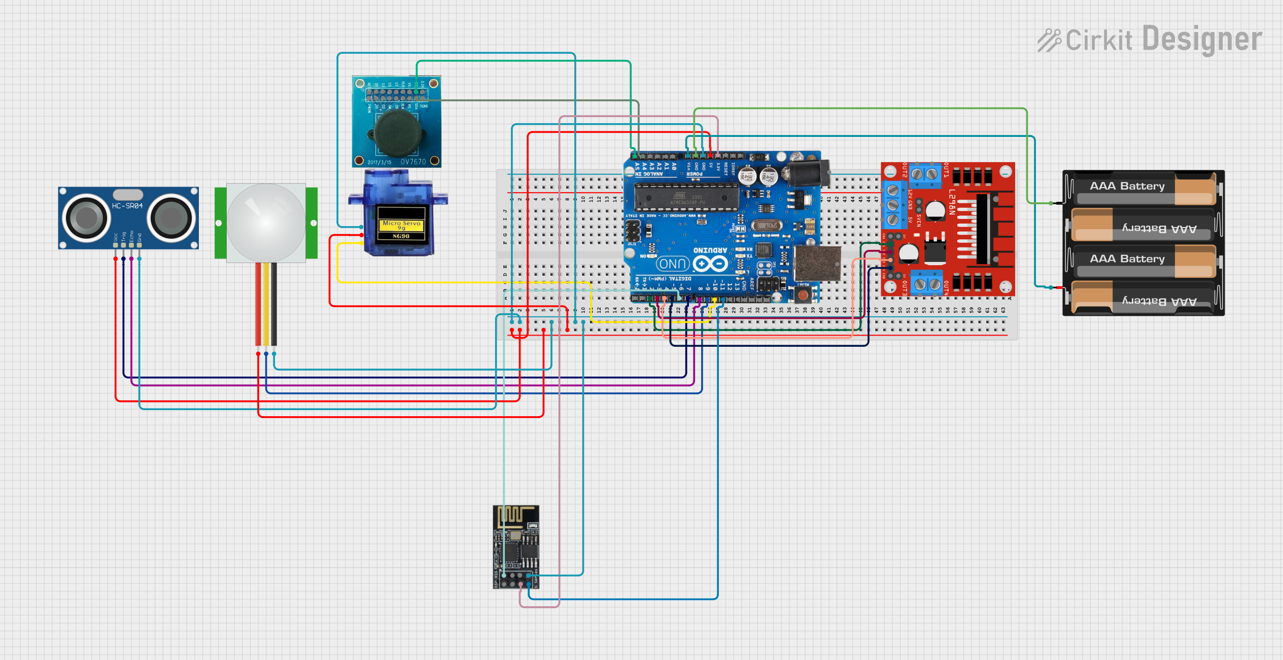
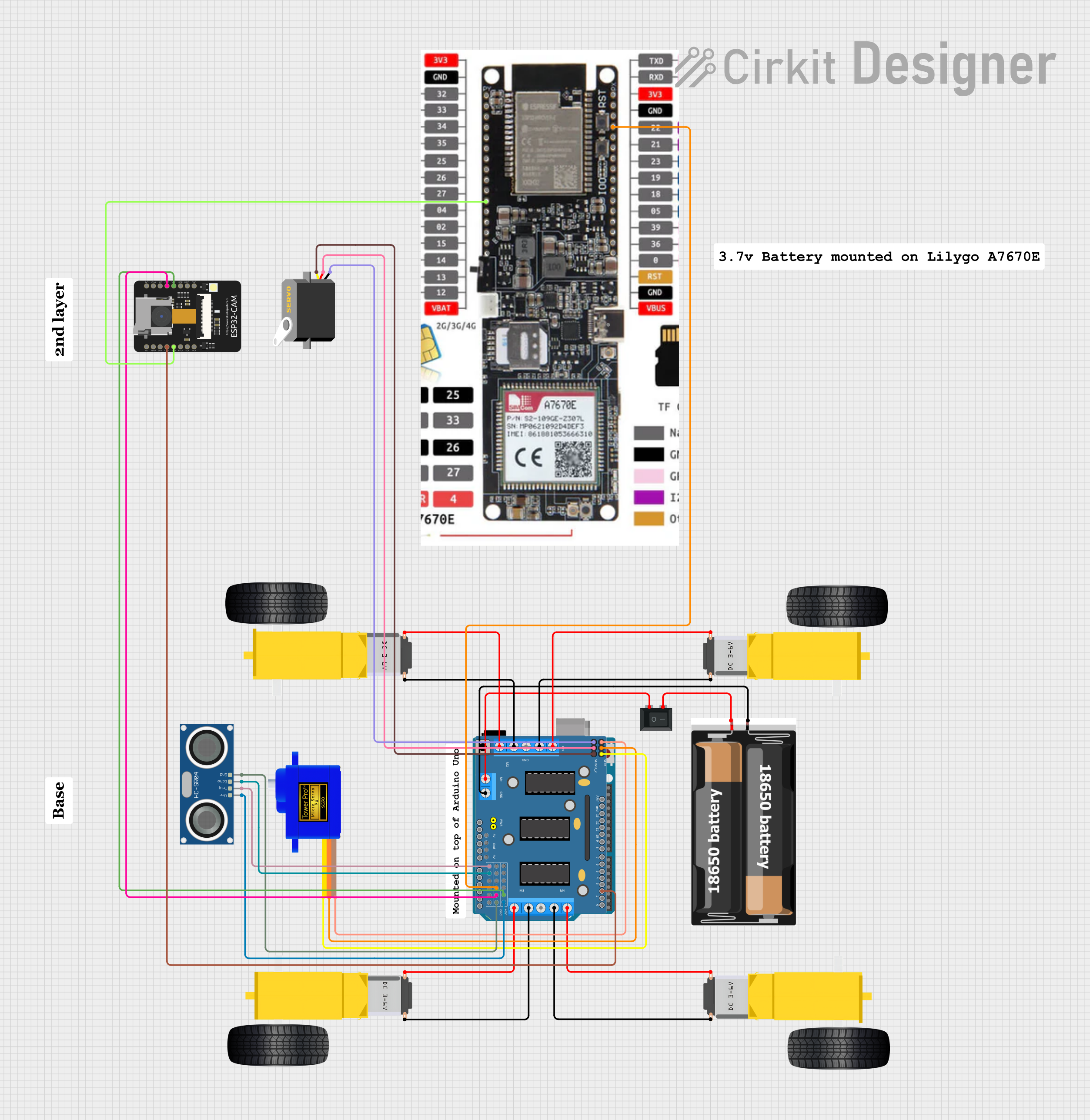
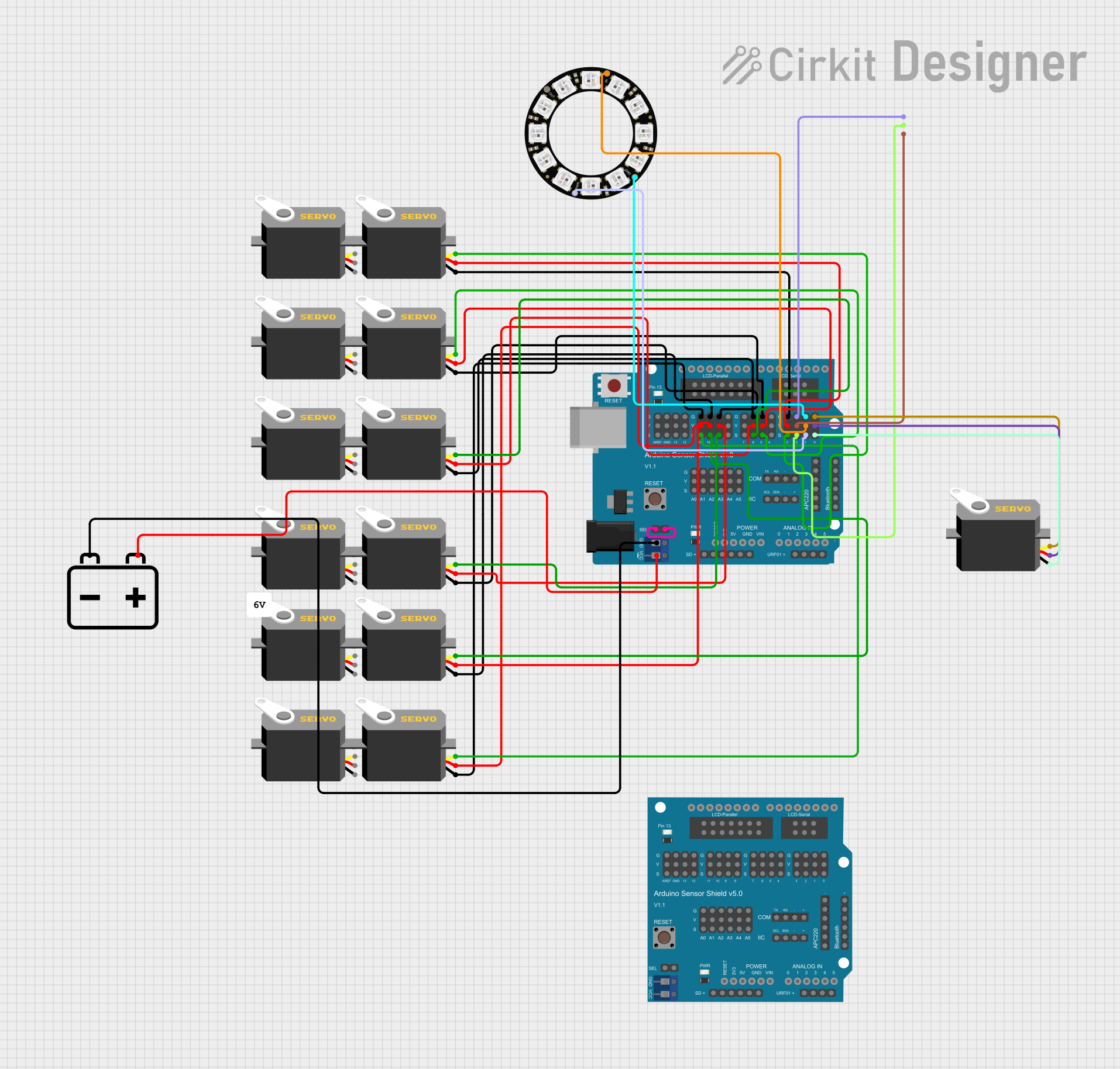
Explore Projects Built with SparkFun_Roshamglo
Common Applications and Use Cases
- Educational Tool: Introduce students to basic programming and electronics.
- Gaming: Use it as a portable game to play rock-paper-scissors.
- Wearable Technology: Wear it as a badge at events or conferences.
- Development Platform: Experiment with custom code and electronics.
Technical Specifications
Key Technical Details
- Microcontroller: ATtiny84
- Operating Voltage: 3V (CR2032 coin cell battery)
- Programming Interface: UPDI (Unified Program and Debug Interface)
- Display: LED matrix
- Input: Two tactile push buttons
- I/O Pins: 12 (multiplexed with LED matrix and buttons)
Pin Configuration and Descriptions
| Pin Number | Function | Description |
|---|---|---|
| 1 | VCC | Power supply (3V) |
| 2 | GND | Ground |
| 3-10 | PB0-PB7 | Digital I/O, multiplexed with LED matrix |
| 11 | Reset/UPDI | Reset pin or UPDI for programming |
| 12 | PA0 | Analog input or digital I/O |
| 13 | PA1 | Analog input or digital I/O, button input |
| 14 | PA2 | Analog input or digital I/O, button input |
Usage Instructions
How to Use the Component in a Circuit
- Powering the Device: Insert a CR2032 coin cell battery into the battery holder.
- Programming: Connect a UPDI programmer to the Reset/UPDI pin to upload your code.
- Playing the Game: Use the push buttons to select rock, paper, or scissors.
Important Considerations and Best Practices
- Battery Life: To conserve battery life, implement a sleep mode in your code.
- Button Debouncing: Implement software debouncing to ensure accurate button presses.
- LED Brightness: Adjust the brightness of the LED matrix to balance visibility and power consumption.
Troubleshooting and FAQs
Common Issues
- Device Not Powering On: Ensure the battery is inserted correctly and has charge.
- Unresponsive Buttons: Check for proper debouncing in the code or hardware issues.
- LED Matrix Not Lighting Up: Verify connections and ensure the LED matrix is properly addressed in the code.
Solutions and Tips for Troubleshooting
- Battery Issues: Replace the battery if the device is not powering on.
- Programming Errors: Double-check the code for errors and ensure the correct board settings in the Arduino IDE.
- Hardware Inspection: Examine the badge for any physical damage or loose connections.
FAQs
Q: How do I program the Roshamglo? A: Use a UPDI programmer and the Arduino IDE with the appropriate board package installed.
Q: Can I modify the game code? A: Yes, the Roshamglo is open for code customization. You can write your own game logic or other applications.
Q: Is the Roshamglo reprogrammable? A: Absolutely, you can reprogram it as many times as you like using the UPDI interface.
Example Code for Arduino UNO
Below is an example code snippet for initializing the LED matrix on the SparkFun Roshamglo. This code is intended for illustrative purposes and assumes you have set up the appropriate board definitions for the ATtiny84 in the Arduino IDE.
#include <avr/power.h>
#include <avr/sleep.h>

// Define the LED matrix and button pins
const int ledPins[] = {3, 4, 5, 6, 7, 8, 9, 10};
const int buttonPins[] = {13, 14};

void setup() {
  // Initialize the LED pins as outputs
  for (int i = 0; i < 8; i++) {
    pinMode(ledPins[i], OUTPUT);
  }

  // Initialize the button pins as inputs with pull-up resistors
  for (int i = 0; i < 2; i++) {
    pinMode(buttonPins[i], INPUT_PULLUP);
  }
}

void loop() {
  // Example code to light up the LED matrix in some pattern
  for (int i = 0; i < 8; i++) {
    digitalWrite(ledPins[i], HIGH); // Turn on each LED
    delay(100);                     // Wait for 100 milliseconds
    digitalWrite(ledPins[i], LOW);  // Turn off each LED
  }
}
Remember to keep the code comments concise and within the 80 character line length limit. This example demonstrates basic initialization and control of the LED matrix and buttons on the Roshamglo badge.