How to Use Voltmeter: Examples, Pinouts, and Specs
Introduction
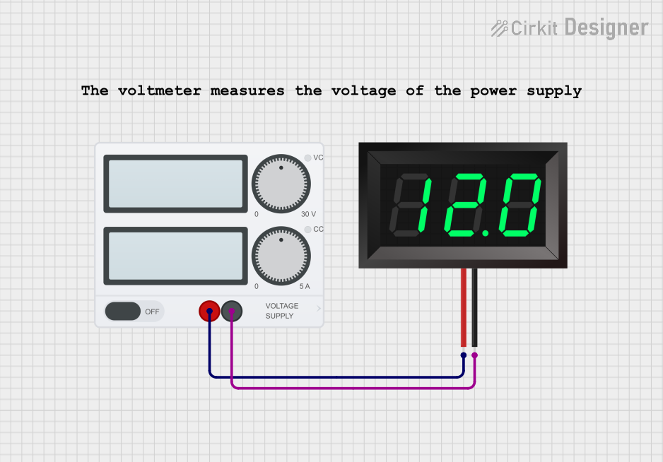
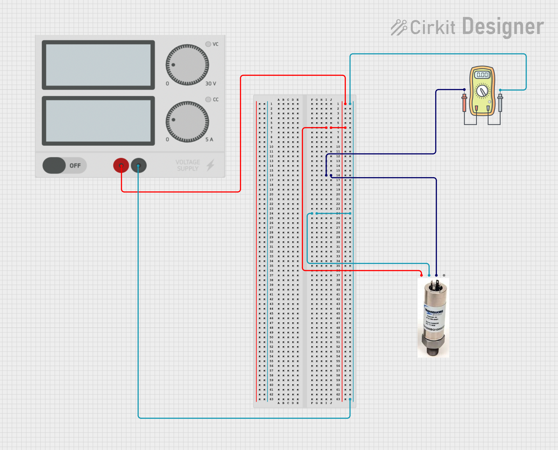
A voltmeter is an instrument used to measure the electrical potential difference, or voltage, between two points in an electrical circuit. It is an essential tool for diagnosing, testing, and monitoring electrical systems. Voltmeters are typically connected in parallel with the component or circuit across which the voltage is to be measured. They are available in both analog and digital forms, with digital voltmeters being more common due to their accuracy and ease of use.
Explore Projects Built with Voltmeter
Explore Projects Built with Voltmeter
Common Applications and Use Cases
- Measuring voltage in electrical circuits for troubleshooting and diagnostics.
- Monitoring battery voltage in automotive and renewable energy systems.
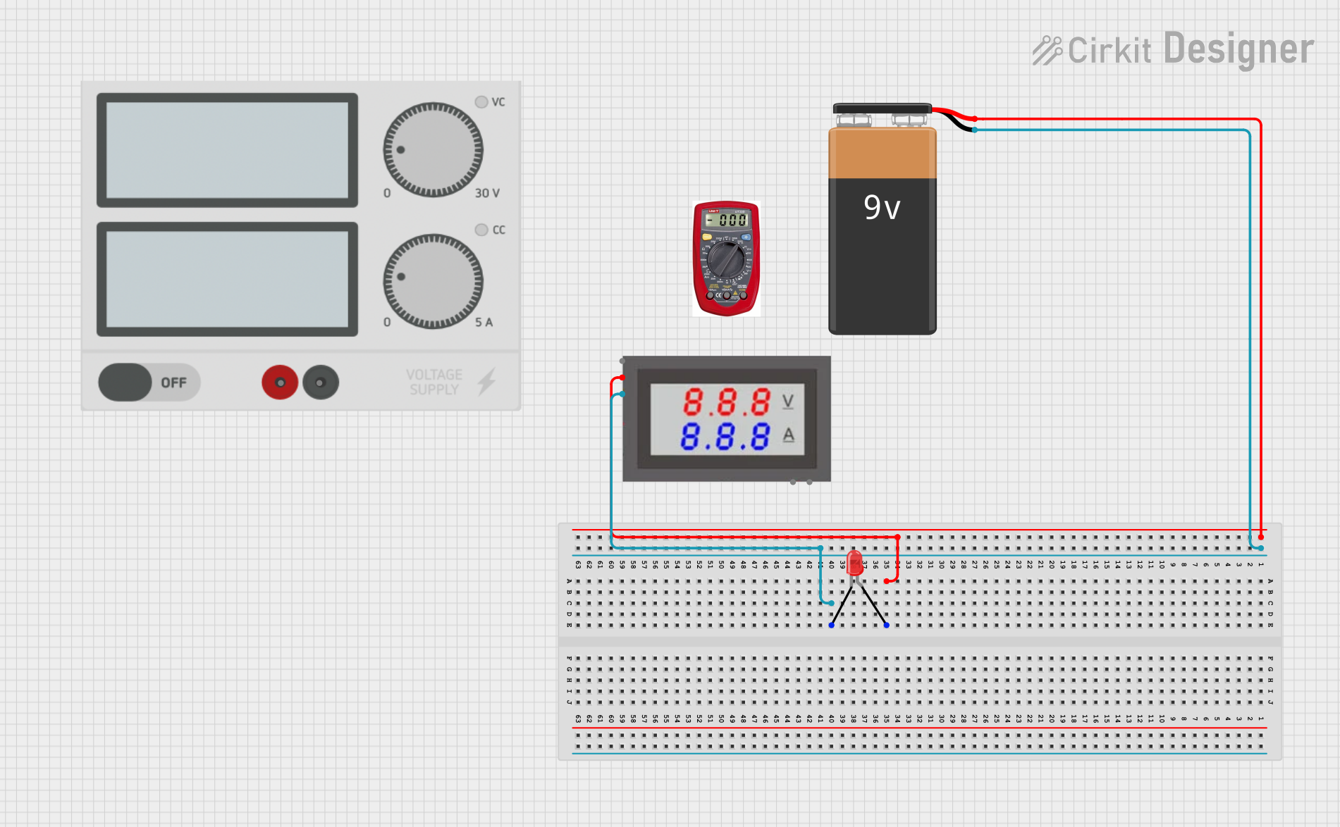
- Testing power supplies and electronic components.
- Educational purposes in electronics labs and training environments.
Technical Specifications
Below are the general technical specifications for a typical digital voltmeter. Note that specific models may vary in their capabilities.
| Specification | Value/Range |
|---|---|
| Voltage Measurement Range | 0V to 1000V (DC), 0V to 750V (AC) |
| Accuracy | ±0.5% of reading (typical) |
| Input Impedance | 1MΩ to 10MΩ |
| Display Type | Digital (LCD/LED) |
| Power Supply | 9V battery or external power source |
| Resolution | 0.1V to 1mV (depending on range) |
| Sampling Rate | 2-3 readings per second |
Pin Configuration and Descriptions
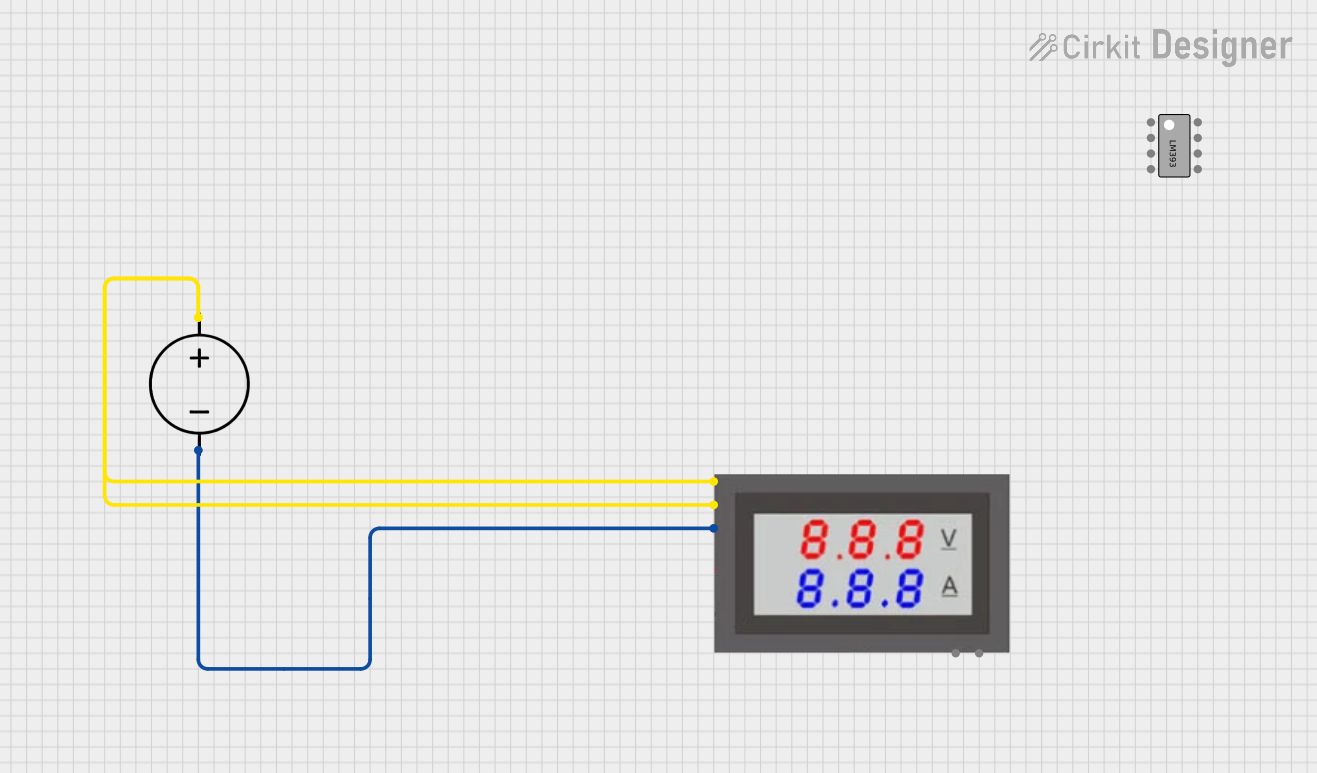
For digital voltmeters with external connections, the pin configuration is as follows:
| Pin Name | Description |
|---|---|
| V+ | Positive voltage input (connect to the circuit) |
| V- | Negative voltage input (connect to ground) |
| COM | Common ground for the voltmeter |
| Power | External power input (if applicable) |
Usage Instructions
How to Use the Voltmeter in a Circuit
- Turn Off the Circuit: Before connecting the voltmeter, ensure the circuit is powered off to avoid damage or incorrect readings.
- Set the Measurement Range: If the voltmeter has a manual range selector, set it to a range higher than the expected voltage.
- Connect the Probes:
- Connect the red probe to the positive terminal (V+).
- Connect the black probe to the negative terminal (V-) or ground.
- Power On the Voltmeter: Turn on the voltmeter and ensure it is functioning correctly.
- Take the Measurement: Power on the circuit and observe the voltage reading on the display.
- Disconnect Safely: After taking the measurement, turn off the circuit and disconnect the probes.
Important Considerations and Best Practices
- Always connect the voltmeter in parallel with the component or circuit being measured.
- Ensure the voltmeter's range is appropriate for the voltage being tested to avoid overloading.
- Avoid touching the probe tips during measurement to prevent inaccurate readings or electric shock.
- For AC voltage measurements, ensure the voltmeter is set to AC mode.
- Regularly check and replace the battery in battery-powered voltmeters to maintain accuracy.
Example: Using a Voltmeter with an Arduino UNO
A voltmeter can be used to measure the output voltage of an Arduino UNO's pins. Below is an example of Arduino code to generate a voltage signal on a PWM pin, which can then be measured using a voltmeter.
// Example: Generating a PWM signal on Arduino UNO for voltage measurement
// Connect the voltmeter probes to the GND and PWM pin (e.g., Pin 9).

int pwmPin = 9; // Define the PWM pin

void setup() {
  pinMode(pwmPin, OUTPUT); // Set the PWM pin as output
}

void loop() {
  analogWrite(pwmPin, 128); // Generate a 50% duty cycle PWM signal
  // The output voltage will be approximately 2.5V on a 5V Arduino UNO.
  delay(1000); // Wait for 1 second
}
Troubleshooting and FAQs
Common Issues and Solutions
No Display or Reading:
- Ensure the voltmeter is powered on and the battery is not depleted.
- Check the probe connections and ensure they are securely attached.
Inaccurate Readings:
- Verify that the voltmeter is set to the correct range and mode (AC/DC).
- Check for damaged probes or loose connections.
- Ensure the input impedance of the voltmeter is appropriate for the circuit.
Overload Indication:
- This occurs when the measured voltage exceeds the selected range. Switch to a higher range.
Fluctuating Readings:
- Ensure stable connections and avoid measuring in noisy environments.
- For AC measurements, ensure the frequency is within the voltmeter's supported range.
FAQs
Q: Can I use a voltmeter to measure current?
A: No, a voltmeter is designed to measure voltage. To measure current, use an ammeter or a multimeter set to current mode.
Q: What happens if I connect the voltmeter in series?
A: Connecting a voltmeter in series can disrupt the circuit and may result in incorrect readings or damage to the voltmeter.
Q: How do I know if my voltmeter is calibrated?
A: Most digital voltmeters are factory-calibrated. For critical applications, periodic calibration by a certified technician is recommended.
Q: Can I measure high voltages with a standard voltmeter?
A: Standard voltmeters have a maximum voltage rating. For high voltages, use a voltmeter rated for the specific range or a voltage divider circuit.