Cirkit Designer Logo
Cirkit Designer
Your all-in-one circuit design IDE
Home / 
Component Documentation

How to Use SPEEDYBEE F405 WING Wires Board Front: Examples, Pinouts, and Specs

Image of SPEEDYBEE F405 WING Wires Board Front
Cirkit Designer LogoDesign with SPEEDYBEE F405 WING Wires Board Front in Cirkit Designer

Introduction

The SPEEDYBEE F405 WING Wires Board Front is a high-performance flight controller designed for fixed-wing and VTOL (Vertical Take-Off and Landing) drones. It is equipped with advanced features such as an F4 processor, multiple UARTs, and integrated OSD (On-Screen Display) for FPV (First-Person View) applications. This board is tailored for drone enthusiasts and professionals who require precise control and reliable performance in their aerial projects.

Explore Projects Built with SPEEDYBEE F405 WING Wires Board Front

Use Cirkit Designer to design, explore, and prototype these projects online. Some projects support real-time simulation. Click "Open Project" to start designing instantly!
GPS-Enabled Telemetry Drone with Speedybee F405 WING and Brushless Motor
Image of Pharmadrone Wiring: A project utilizing SPEEDYBEE F405 WING Wires Board Front in a practical application
This circuit is designed for a remote-controlled vehicle or drone, featuring a flight controller that manages a brushless motor, servomotors for actuation, telemetry for data communication, and a GPS module for positioning. It is powered by a lipo battery and includes a receiver for remote control inputs.
Cirkit Designer LogoOpen Project in Cirkit Designer
Battery-Powered FPV Drone with Telemetry and Dual Motor Control
Image of Krul': A project utilizing SPEEDYBEE F405 WING Wires Board Front in a practical application
This circuit appears to be a power distribution and control system for a vehicle with two motorized wheels, possibly a drone or a robot. It includes a lipo battery connected to a Power Distribution Board (PDB) that distributes power to two Electronic Speed Controllers (ESCs) which in turn control the speed and direction of the motors. The system also integrates a flight controller (H743-SLIM V3) for managing various peripherals including GPS, FPV camera system, and a telemetry link (ExpressLRS).
Cirkit Designer LogoOpen Project in Cirkit Designer
Battery-Powered Motor Control System with BTS7960 and Fly Sky Receiver
Image of BTS motor Driver: A project utilizing SPEEDYBEE F405 WING Wires Board Front in a practical application
This circuit is designed to control two 775 motors using BTS7960 motor drivers, an electronic speed controller (ESC), and a Fly Sky receiver. The Fly Sky receiver receives control signals and distributes them to the motor drivers and servo internal circuits, which in turn control the motors. Power is supplied by a 2200mAh LiPo battery.
Cirkit Designer LogoOpen Project in Cirkit Designer
Raspberry Pi-Controlled Drone with Brushless Motors and Camera Module
Image of ROV: A project utilizing SPEEDYBEE F405 WING Wires Board Front in a practical application
This circuit is designed for a multi-motor application, likely a drone or a similar vehicle, featuring eight brushless motors controlled by two 4-in-1 electronic speed controllers (ESCs). The ESCs are powered by a 3s2p 18650 battery pack and interfaced with a Pixhawk flight controller for motor management. Additionally, the system includes a Raspberry Pi 4B for advanced processing and control, which is connected to a NoIR camera module and a cooling fan, and a power module to supply and monitor the power to the Pixhawk.
Cirkit Designer LogoOpen Project in Cirkit Designer

Explore Projects Built with SPEEDYBEE F405 WING Wires Board Front

Use Cirkit Designer to design, explore, and prototype these projects online. Some projects support real-time simulation. Click "Open Project" to start designing instantly!
Image of Pharmadrone Wiring: A project utilizing SPEEDYBEE F405 WING Wires Board Front in a practical application
GPS-Enabled Telemetry Drone with Speedybee F405 WING and Brushless Motor
This circuit is designed for a remote-controlled vehicle or drone, featuring a flight controller that manages a brushless motor, servomotors for actuation, telemetry for data communication, and a GPS module for positioning. It is powered by a lipo battery and includes a receiver for remote control inputs.
Cirkit Designer LogoOpen Project in Cirkit Designer
Image of Krul': A project utilizing SPEEDYBEE F405 WING Wires Board Front in a practical application
Battery-Powered FPV Drone with Telemetry and Dual Motor Control
This circuit appears to be a power distribution and control system for a vehicle with two motorized wheels, possibly a drone or a robot. It includes a lipo battery connected to a Power Distribution Board (PDB) that distributes power to two Electronic Speed Controllers (ESCs) which in turn control the speed and direction of the motors. The system also integrates a flight controller (H743-SLIM V3) for managing various peripherals including GPS, FPV camera system, and a telemetry link (ExpressLRS).
Cirkit Designer LogoOpen Project in Cirkit Designer
Image of BTS motor Driver: A project utilizing SPEEDYBEE F405 WING Wires Board Front in a practical application
Battery-Powered Motor Control System with BTS7960 and Fly Sky Receiver
This circuit is designed to control two 775 motors using BTS7960 motor drivers, an electronic speed controller (ESC), and a Fly Sky receiver. The Fly Sky receiver receives control signals and distributes them to the motor drivers and servo internal circuits, which in turn control the motors. Power is supplied by a 2200mAh LiPo battery.
Cirkit Designer LogoOpen Project in Cirkit Designer
Image of ROV: A project utilizing SPEEDYBEE F405 WING Wires Board Front in a practical application
Raspberry Pi-Controlled Drone with Brushless Motors and Camera Module
This circuit is designed for a multi-motor application, likely a drone or a similar vehicle, featuring eight brushless motors controlled by two 4-in-1 electronic speed controllers (ESCs). The ESCs are powered by a 3s2p 18650 battery pack and interfaced with a Pixhawk flight controller for motor management. Additionally, the system includes a Raspberry Pi 4B for advanced processing and control, which is connected to a NoIR camera module and a cooling fan, and a power module to supply and monitor the power to the Pixhawk.
Cirkit Designer LogoOpen Project in Cirkit Designer

Common Applications and Use Cases

  • Fixed-wing drones for recreational or professional use
  • VTOL drones for advanced aerial operations
  • FPV systems with integrated OSD for real-time telemetry
  • Autonomous flight systems with GPS and telemetry modules
  • Long-range UAVs requiring multiple UARTs for peripherals

Technical Specifications

Key Technical Details

  • Processor: STM32F405 (F4 series, 32-bit ARM Cortex-M4)
  • Input Voltage: 7V–36V (2S–8S LiPo battery)
  • BEC Output: 5V/2A and 9V/2A
  • UART Ports: 6 UARTs for peripherals (GPS, telemetry, etc.)
  • IMU: MPU6000 (6-axis gyroscope and accelerometer)
  • OSD: Integrated Betaflight OSD
  • Flash Memory: 16MB for Blackbox logging
  • PWM Outputs: 8 PWM outputs for servos or ESCs
  • Dimensions: 50mm x 50mm
  • Mounting Holes: 30.5mm x 30.5mm (standard M3 screws)

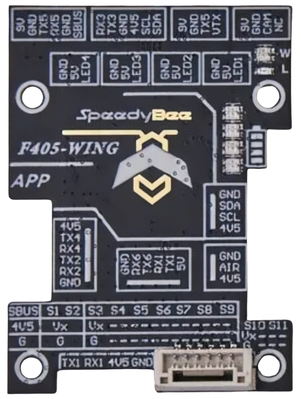
Pin Configuration and Descriptions

The SPEEDYBEE F405 WING Wires Board Front features a variety of pins for connecting peripherals. Below is the pinout description:

Pin Name Description
GND Ground connection
VBAT Battery voltage input (7V–36V)
5V 5V output for peripherals
9V 9V output for FPV camera or VTX
UART1 TX/RX UART1 for GPS or telemetry
UART2 TX/RX UART2 for additional peripherals
UART3 TX/RX UART3 for receiver or telemetry
UART4 TX/RX UART4 for FPV camera control
UART5 TX/RX UART5 for additional peripherals
UART6 TX/RX UART6 for external modules
PWM1–PWM8 PWM outputs for servos or ESCs
RSSI Analog RSSI input for receiver signal
SCL/SDA I2C interface for external sensors
BOOT Bootloader mode selection

Usage Instructions

How to Use the Component in a Circuit

  1. Powering the Board: Connect a 2S–8S LiPo battery to the VBAT pin. Ensure the voltage is within the 7V–36V range.
  2. Connecting Peripherals:
    • Use the UART ports to connect GPS, telemetry modules, or receivers.
    • Connect FPV cameras and VTX modules to the 9V output for stable power.
    • Attach servos or ESCs to the PWM outputs for motor control.
  3. Configuring the Board:
    • Use Betaflight Configurator to set up the flight controller.
    • Assign UART ports to specific peripherals in the configuration tool.
    • Calibrate the IMU and set up the OSD for telemetry display.
  4. Mounting: Secure the board using M3 screws and ensure proper vibration isolation.

Important Considerations and Best Practices

  • Voltage Compatibility: Always verify the input voltage to avoid damaging the board.
  • Peripheral Connections: Double-check the pinout to ensure correct wiring of peripherals.
  • Firmware Updates: Keep the firmware updated via Betaflight Configurator for optimal performance.
  • Heat Management: Ensure proper airflow around the board to prevent overheating during operation.

Example Code for Arduino UNO Integration

Although the SPEEDYBEE F405 WING is not typically used with an Arduino UNO, you can use an Arduino to send telemetry data to the board via UART. Below is an example:

#include <SoftwareSerial.h>

// Define RX and TX pins for SoftwareSerial
SoftwareSerial telemetrySerial(10, 11); // RX = pin 10, TX = pin 11

void setup() {
  // Initialize serial communication
  Serial.begin(9600); // Default serial monitor
  telemetrySerial.begin(9600); // UART communication with SPEEDYBEE F405

  // Print initialization message
  Serial.println("Arduino to SPEEDYBEE F405 telemetry example");
}

void loop() {
  // Send telemetry data to SPEEDYBEE F405
  telemetrySerial.println("Telemetry data from Arduino");

  // Check for incoming data from SPEEDYBEE F405
  if (telemetrySerial.available()) {
    String data = telemetrySerial.readString();
    Serial.println("Received from SPEEDYBEE: " + data);
  }

  delay(1000); // Delay for 1 second
}

Troubleshooting and FAQs

Common Issues Users Might Face

  1. Board Not Powering On:

    • Cause: Incorrect input voltage or loose connections.
    • Solution: Verify the battery voltage and ensure secure connections to the VBAT pin.
  2. No Communication with Peripherals:

    • Cause: Incorrect UART configuration or wiring.
    • Solution: Check the Betaflight Configurator settings and verify the pin connections.
  3. OSD Not Displaying:

    • Cause: Misconfigured OSD settings or incompatible FPV camera.
    • Solution: Reconfigure the OSD in Betaflight and ensure the camera is connected to the correct pins.
  4. Overheating:

    • Cause: Insufficient airflow or excessive current draw.
    • Solution: Improve ventilation and ensure peripherals do not exceed the board's power limits.

Solutions and Tips for Troubleshooting

  • Use a multimeter to check voltage levels at the pins.
  • Update the firmware to the latest version to resolve software-related issues.
  • Refer to the official SPEEDYBEE documentation for advanced troubleshooting steps.