How to Use Nokia 5110: Examples, Pinouts, and Specs
Introduction
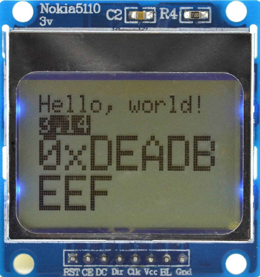
The Nokia 5110 is a compact, monochrome LCD display module with a resolution of 84x48 pixels. Originally designed for Nokia mobile phones, this display has become a popular choice for embedded systems and DIY electronics projects due to its low power consumption, affordability, and ease of use. It communicates via SPI (Serial Peripheral Interface) or parallel communication, making it compatible with a wide range of microcontrollers.
Explore Projects Built with Nokia 5110
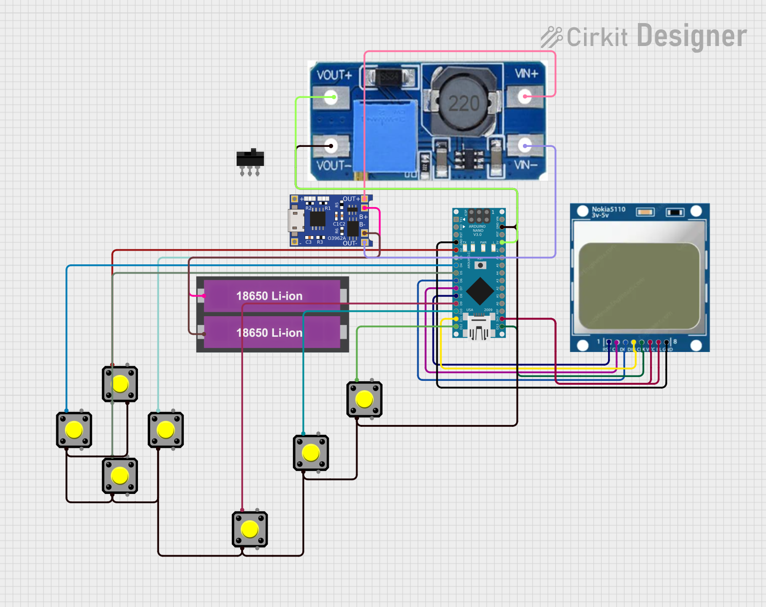
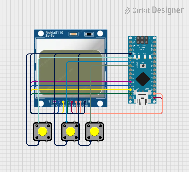
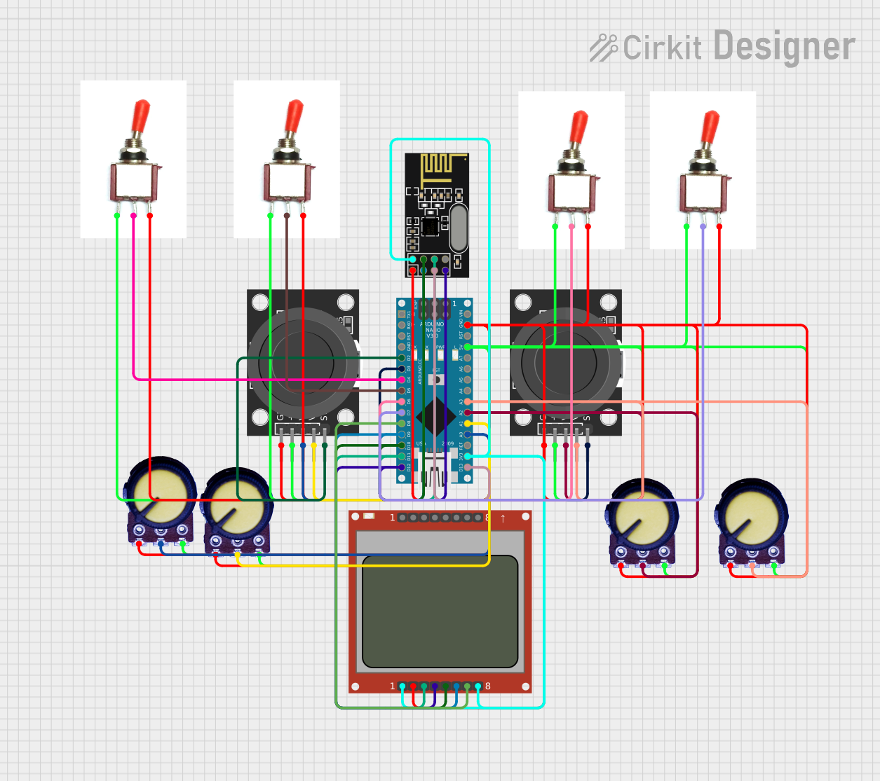
Explore Projects Built with Nokia 5110
Common Applications and Use Cases
- Displaying text, graphics, and simple animations in embedded systems
- DIY electronics projects and prototyping
- Battery-powered devices due to its low power consumption
- Educational projects for learning SPI communication
- Wearable devices and compact user interfaces
Technical Specifications
The Nokia 5110 LCD module has the following key technical specifications:
| Parameter | Value |
|---|---|
| Resolution | 84x48 pixels |
| Communication Interface | SPI or Parallel |
| Operating Voltage | 2.7V to 3.3V |
| Backlight | LED (optional, varies by module) |
| Power Consumption | ~0.4mA (without backlight) |
| Controller IC | PCD8544 |
| Dimensions | ~45mm x 45mm x 5mm |
Pin Configuration and Descriptions
The Nokia 5110 module typically has 8 pins. Below is the pinout and description:
| Pin | Name | Description |
|---|---|---|
| 1 | RST | Reset pin. Active LOW. Resets the display controller. |
| 2 | CE | Chip Enable. Active LOW. Enables communication with the display. |
| 3 | DC | Data/Command. HIGH for data, LOW for command. |
| 4 | DIN | Data Input. Serial data input for SPI communication. |
| 5 | CLK | Clock. Serial clock input for SPI communication. |
| 6 | VCC | Power supply. Connect to 3.3V. |
| 7 | BL | Backlight. Connect to a resistor and power source to enable the backlight (optional). |
| 8 | GND | Ground. Connect to the ground of the circuit. |
Note: Some modules may not include a backlight pin (BL). Check your specific module for details.
Usage Instructions
How to Use the Nokia 5110 in a Circuit
- Power Supply: Connect the VCC pin to a 3.3V power source. Do not exceed 3.3V as the module is not 5V tolerant.
- SPI Communication: Connect the DIN, CLK, CE, and DC pins to the corresponding SPI pins on your microcontroller.
- Backlight (Optional): If your module has a backlight pin (BL), connect it to a resistor (e.g., 330Ω) and then to a power source (3.3V or 5V, depending on your module).
- Reset: Connect the RST pin to a GPIO pin on your microcontroller for resetting the display.
- Ground: Connect the GND pin to the ground of your circuit.
Important Considerations and Best Practices
- Voltage Levels: The Nokia 5110 operates at 3.3V. If using a 5V microcontroller (e.g., Arduino UNO), use level shifters or resistors to step down the voltage on the SPI lines.
- Backlight Power: If using the backlight, ensure the current is limited by a resistor to prevent damage.
- Initialization: The display requires proper initialization commands to function. Use a library or refer to the PCD8544 datasheet for details.
Example Code for Arduino UNO
Below is an example of how to use the Nokia 5110 with an Arduino UNO using the popular Adafruit_PCD8544 library:
#include <Adafruit_GFX.h>       // Core graphics library
#include <Adafruit_PCD8544.h>   // Nokia 5110 library

// Pin definitions for the Nokia 5110
#define RST_PIN  8  // Reset pin
#define CE_PIN   7  // Chip Enable pin
#define DC_PIN   6  // Data/Command pin
#define DIN_PIN  5  // Data Input pin (MOSI)
#define CLK_PIN  4  // Clock pin (SCK)

// Create an instance of the display
Adafruit_PCD8544 display = Adafruit_PCD8544(CLK_PIN, DIN_PIN, DC_PIN, CE_PIN, RST_PIN);

void setup() {
  // Initialize the display
  display.begin();
  display.setContrast(50);  // Adjust contrast (0-127)

  // Clear the display buffer
  display.clearDisplay();

  // Display a message
  display.setTextSize(1);       // Set text size
  display.setTextColor(BLACK); // Set text color
  display.setCursor(0, 0);      // Set cursor position
  display.println("Hello, World!");
  display.display();            // Update the display
}

void loop() {
  // Nothing to do here
}
Note: Install the
Adafruit_GFXandAdafruit_PCD8544libraries via the Arduino Library Manager before running the code.
Troubleshooting and FAQs
Common Issues and Solutions
Display Not Turning On
- Ensure the VCC and GND connections are correct.
- Verify that the power supply is 3.3V. If using a 5V microcontroller, use level shifters.
No Output on the Display
- Check the SPI connections (DIN, CLK, CE, DC).
- Ensure the RST pin is properly connected and initialized in the code.
- Verify that the display is initialized with the correct commands or library.
Faint or No Backlight
- Ensure the backlight pin (BL) is connected to a resistor and power source.
- Check the resistor value to ensure proper current limiting.
Corrupted or Flickering Display
- Verify the SPI clock speed. The Nokia 5110 typically supports up to 4MHz.
- Check for loose or poor connections in the circuit.
FAQs
Q: Can I use the Nokia 5110 with a 5V microcontroller?
A: Yes, but you must use level shifters or resistors to step down the voltage on the SPI lines to 3.3V.
Q: How do I adjust the contrast of the display?
A: Use the setContrast() function in your code. The contrast value typically ranges from 0 to 127.
Q: Can I display images on the Nokia 5110?
A: Yes, you can display monochrome bitmaps. Use tools like LCD Assistant to convert images to the required format.
Q: Is the backlight necessary for the display to work?
A: No, the backlight is optional and only enhances visibility in low-light conditions.