Cirkit Designer Logo
Cirkit Designer
Your all-in-one circuit design IDE
Home / 
Component Documentation

How to Use RF Pack S3: Examples, Pinouts, and Specs

Image of RF Pack S3
Cirkit Designer LogoDesign with RF Pack S3 in Cirkit Designer

Introduction

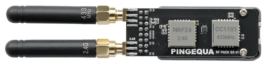
The RF Pack S3, manufactured by Pingequa, is a high-performance radio frequency (RF) module designed for wireless communication applications. It enables efficient transmission and reception of RF signals across various frequency bands, making it a versatile solution for a wide range of projects. With its compact design and robust functionality, the RF Pack S3 is ideal for IoT devices, remote controls, wireless sensors, and other RF-based systems.

Explore Projects Built with RF Pack S3

Use Cirkit Designer to design, explore, and prototype these projects online. Some projects support real-time simulation. Click "Open Project" to start designing instantly!
Satellite-Based Timing and Navigation System with SDR and Atomic Clock Synchronization
Image of GPS 시스템 측정 구성도_Confirm: A project utilizing RF Pack S3 in a practical application
This circuit appears to be a complex system involving power supply management, GPS and timing synchronization, and data communication. It includes a SI-TEX G1 Satellite Compass for GPS data, an XHTF1021 Atomic Rubidium Clock for precise timing, and Ettus USRP B200 units for software-defined radio communication. Power is supplied through various SMPS units and distributed via terminal blocks and DC jacks. Data communication is facilitated by Beelink MINI S12 N95 computers, RS232 splitters, and a 1000BASE-T Media Converter for network connectivity. RF Directional Couplers are used to interface antennas with the USRP units, and the entire system is likely contained within cases for protection and organization.
Cirkit Designer LogoOpen Project in Cirkit Designer
Dual-Mode LoRa and GSM Communication Device with ESP32
Image of modul gateway: A project utilizing RF Pack S3 in a practical application
This circuit features an ESP32 Devkit V1 microcontroller interfaced with an RFM95 LoRa transceiver module for long-range communication and a SIM800L GSM module for cellular connectivity. Two LM2596 step-down modules are used to regulate the 12V battery voltage down to 3.3V required by the ESP32, RFM95, and SIM800L. The ESP32 facilitates data exchange between the RFM95 and SIM800L, enabling the system to send/receive data over both LoRa and GSM networks.
Cirkit Designer LogoOpen Project in Cirkit Designer
NFC-Enabled Access Control System with Time Logging
Image of doorlock: A project utilizing RF Pack S3 in a practical application
This circuit is designed for access control with time tracking capabilities. It features an NFC/RFID reader for authentication, an RTC module (DS3231) for real-time clock functionality, and an OLED display for user interaction. A 12V relay controls a magnetic lock, which is activated upon successful NFC/RFID authentication, and a button switch is likely used for manual operation or input. The T8_S3 microcontroller serves as the central processing unit, interfacing with the NFC/RFID reader, RTC, OLED, and relay to manage the access control logic.
Cirkit Designer LogoOpen Project in Cirkit Designer
Arduino Nano Controlled RF Receiver with SD Logging and Audio Output
Image of Teacher Helping: A project utilizing RF Pack S3 in a practical application
This is a wireless audio playback system featuring an Arduino Nano interfaced with an RF receiver for signal acquisition, an SD card module for audio data storage, and a PAM8403 amplifier to drive stereo loudspeakers. The system is powered by a 18650 Li-Ion battery with a 7805 regulator for voltage stabilization, and a rocker switch for power control.
Cirkit Designer LogoOpen Project in Cirkit Designer

Explore Projects Built with RF Pack S3

Use Cirkit Designer to design, explore, and prototype these projects online. Some projects support real-time simulation. Click "Open Project" to start designing instantly!
Image of GPS 시스템 측정 구성도_Confirm: A project utilizing RF Pack S3 in a practical application
Satellite-Based Timing and Navigation System with SDR and Atomic Clock Synchronization
This circuit appears to be a complex system involving power supply management, GPS and timing synchronization, and data communication. It includes a SI-TEX G1 Satellite Compass for GPS data, an XHTF1021 Atomic Rubidium Clock for precise timing, and Ettus USRP B200 units for software-defined radio communication. Power is supplied through various SMPS units and distributed via terminal blocks and DC jacks. Data communication is facilitated by Beelink MINI S12 N95 computers, RS232 splitters, and a 1000BASE-T Media Converter for network connectivity. RF Directional Couplers are used to interface antennas with the USRP units, and the entire system is likely contained within cases for protection and organization.
Cirkit Designer LogoOpen Project in Cirkit Designer
Image of modul gateway: A project utilizing RF Pack S3 in a practical application
Dual-Mode LoRa and GSM Communication Device with ESP32
This circuit features an ESP32 Devkit V1 microcontroller interfaced with an RFM95 LoRa transceiver module for long-range communication and a SIM800L GSM module for cellular connectivity. Two LM2596 step-down modules are used to regulate the 12V battery voltage down to 3.3V required by the ESP32, RFM95, and SIM800L. The ESP32 facilitates data exchange between the RFM95 and SIM800L, enabling the system to send/receive data over both LoRa and GSM networks.
Cirkit Designer LogoOpen Project in Cirkit Designer
Image of doorlock: A project utilizing RF Pack S3 in a practical application
NFC-Enabled Access Control System with Time Logging
This circuit is designed for access control with time tracking capabilities. It features an NFC/RFID reader for authentication, an RTC module (DS3231) for real-time clock functionality, and an OLED display for user interaction. A 12V relay controls a magnetic lock, which is activated upon successful NFC/RFID authentication, and a button switch is likely used for manual operation or input. The T8_S3 microcontroller serves as the central processing unit, interfacing with the NFC/RFID reader, RTC, OLED, and relay to manage the access control logic.
Cirkit Designer LogoOpen Project in Cirkit Designer
Image of Teacher Helping: A project utilizing RF Pack S3 in a practical application
Arduino Nano Controlled RF Receiver with SD Logging and Audio Output
This is a wireless audio playback system featuring an Arduino Nano interfaced with an RF receiver for signal acquisition, an SD card module for audio data storage, and a PAM8403 amplifier to drive stereo loudspeakers. The system is powered by a 18650 Li-Ion battery with a 7805 regulator for voltage stabilization, and a rocker switch for power control.
Cirkit Designer LogoOpen Project in Cirkit Designer

Common Applications

  • Internet of Things (IoT) devices
  • Wireless sensor networks
  • Remote control systems
  • Home automation
  • Industrial monitoring and control
  • Wireless data transmission in embedded systems

Technical Specifications

The RF Pack S3 is engineered to deliver reliable performance in demanding environments. Below are its key technical specifications:

Parameter Specification
Operating Voltage 3.3V to 5.0V
Operating Frequency 433 MHz, 868 MHz, or 915 MHz
Transmission Power Up to 20 dBm
Sensitivity -120 dBm
Communication Protocol SPI
Data Rate Up to 300 kbps
Operating Temperature -40°C to +85°C
Dimensions 25 mm x 15 mm x 3 mm

Pin Configuration

The RF Pack S3 features an 8-pin interface for easy integration into your circuit. Below is the pinout description:

Pin Name Description
1 VCC Power supply input (3.3V to 5.0V)
2 GND Ground connection
3 MOSI SPI Master Out Slave In
4 MISO SPI Master In Slave Out
5 SCK SPI Clock
6 CS Chip Select (active low)
7 IRQ Interrupt request output
8 ANT Antenna connection for RF signal transmission/reception

Usage Instructions

How to Use the RF Pack S3 in a Circuit

  1. Power Supply: Connect the VCC pin to a regulated 3.3V or 5.0V power source and the GND pin to the ground.
  2. SPI Communication: Interface the RF Pack S3 with a microcontroller (e.g., Arduino UNO) using the SPI pins (MOSI, MISO, SCK, and CS).
  3. Antenna Connection: Attach a suitable antenna to the ANT pin to ensure optimal RF signal transmission and reception.
  4. Interrupt Handling: Use the IRQ pin to handle interrupts for events such as data reception or transmission completion.

Important Considerations

  • Use decoupling capacitors (e.g., 0.1 µF) near the VCC pin to reduce noise and ensure stable operation.
  • Ensure the antenna is tuned to the operating frequency band (433 MHz, 868 MHz, or 915 MHz) for maximum efficiency.
  • Avoid placing the module near high-frequency noise sources or metal enclosures that may interfere with RF signals.
  • Follow local regulations for RF transmission power and frequency usage.

Example: Connecting RF Pack S3 to Arduino UNO

Below is an example of how to connect and program the RF Pack S3 with an Arduino UNO for basic communication:
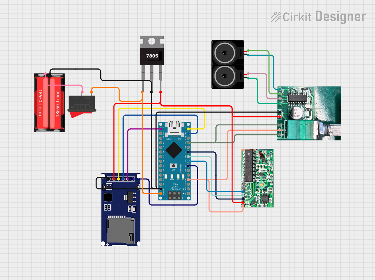
Wiring Diagram

RF Pack S3 Pin Arduino UNO Pin
VCC 3.3V
GND GND
MOSI D11
MISO D12
SCK D13
CS D10
IRQ D2

Arduino Code Example

#include <SPI.h>

// Define RF Pack S3 pins
#define CS_PIN 10  // Chip Select pin
#define IRQ_PIN 2  // Interrupt pin

void setup() {
  // Initialize serial communication for debugging
  Serial.begin(9600);
  
  // Configure SPI and RF Pack S3 pins
  pinMode(CS_PIN, OUTPUT);
  pinMode(IRQ_PIN, INPUT);
  digitalWrite(CS_PIN, HIGH); // Set CS pin high (inactive)

  // Initialize SPI
  SPI.begin();
  Serial.println("RF Pack S3 initialized.");
}

void loop() {
  // Example: Send a test command to the RF Pack S3
  digitalWrite(CS_PIN, LOW); // Activate CS pin
  SPI.transfer(0x01);        // Send a dummy command (replace with actual command)
  digitalWrite(CS_PIN, HIGH); // Deactivate CS pin

  // Wait for interrupt signal (if applicable)
  if (digitalRead(IRQ_PIN) == LOW) {
    Serial.println("Interrupt received from RF Pack S3.");
  }

  delay(1000); // Wait 1 second before repeating
}

Troubleshooting and FAQs

Common Issues and Solutions

  1. No RF Signal Detected

    • Ensure the antenna is properly connected and tuned to the correct frequency band.
    • Verify the power supply voltage is within the specified range (3.3V to 5.0V).
    • Check SPI connections and ensure the microcontroller is configured correctly.
  2. Intermittent Communication

    • Use decoupling capacitors near the power supply pins to reduce noise.
    • Avoid placing the module near sources of electromagnetic interference (EMI).
  3. Module Not Responding

    • Confirm that the CS pin is being toggled correctly during SPI communication.
    • Check for loose or incorrect wiring connections.

FAQs

Q: Can the RF Pack S3 operate at 2.4 GHz?
A: No, the RF Pack S3 is designed to operate at 433 MHz, 868 MHz, or 915 MHz frequency bands.

Q: What type of antenna should I use?
A: Use a monopole or dipole antenna tuned to the operating frequency band for optimal performance.

Q: Is the RF Pack S3 compatible with 5V logic?
A: Yes, the RF Pack S3 supports both 3.3V and 5V logic levels, making it compatible with most microcontrollers.

Q: Can I use multiple RF Pack S3 modules in the same area?
A: Yes, but ensure each module operates on a unique address or channel to avoid interference.