How to Use Flora LSM303 Compass+Accel: Examples, Pinouts, and Specs
Introduction
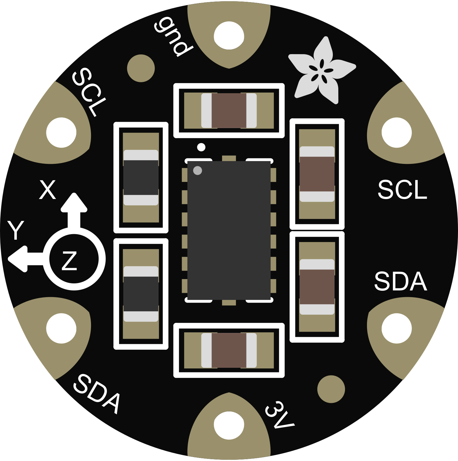
The Flora LSM303 Compass+Accel is a compact and versatile sensor module that integrates both a 3-axis accelerometer and a 3-axis magnetometer. This sensor is designed for motion detection, orientation tracking, and magnetic field measurement, making it ideal for wearable technology, navigation systems, and gesture recognition applications.
Explore Projects Built with Flora LSM303 Compass+Accel
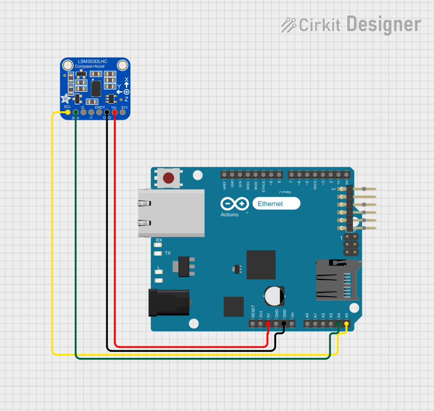

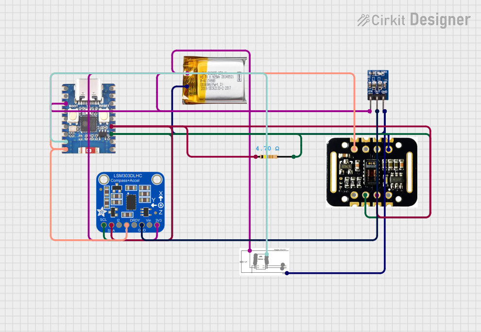
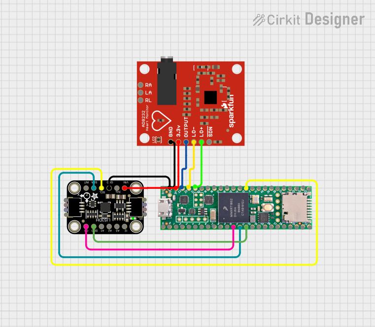
Explore Projects Built with Flora LSM303 Compass+Accel
Common Applications and Use Cases
- Wearable Devices: Integration into smartwatches, fitness trackers, and other wearable technology for activity monitoring.
- Navigation Systems: Providing heading information for handheld compasses and GPS devices.
- Gesture Recognition: Detecting movements and gestures in gaming and interactive installations.
- Robotics: Assisting in balance control and navigation for robots and drones.
Technical Specifications
Key Technical Details
- Supply Voltage: 3.3V
- Operating Current: 10 μA (low-power mode)
- Accelerometer Range: ±2/±4/±8/±16 g
- Magnetometer Range: ±1.3/±1.9/±2.5/±4.0/±4.7/±5.6/±8.1 gauss
- Communication Interface: I2C
- Operating Temperature Range: -30°C to +85°C
Pin Configuration and Descriptions
| Pin Number | Name | Description |
|---|---|---|
| 1 | SCL | I2C clock line for communication with microcontrollers |
| 2 | SDA | I2C data line for communication with microcontrollers |
| 3 | VCC | Power supply (3.3V) |
| 4 | GND | Ground connection |
Usage Instructions
How to Use the Component in a Circuit
- Power Connections: Connect the VCC pin to a 3.3V source and the GND pin to the ground on your microcontroller board.
- Data Connections: Connect the SCL and SDA pins to the corresponding I2C pins on your microcontroller.
- Initialization: Initialize the sensor using the appropriate library for your microcontroller.
Important Considerations and Best Practices
- Voltage Levels: Ensure that the power supply is 3.3V, as higher voltages may damage the sensor.
- I2C Addressing: Be aware of the I2C address of the LSM303 to avoid conflicts with other I2C devices.
- Calibration: Calibrate the magnetometer for accurate readings, especially if the sensor is placed near ferrous materials.
- Library Usage: Utilize existing libraries and drivers to simplify development and ensure proper sensor operation.
Example Code for Arduino UNO
#include <Wire.h>
#include <Adafruit_Sensor.h>
#include <Adafruit_LSM303_U.h>

/* Assign a unique ID to the sensors */
Adafruit_LSM303_Accel_Unified accel = Adafruit_LSM303_Accel_Unified(54321);
Adafruit_LSM303_Mag_Unified mag = Adafruit_LSM303_Mag_Unified(12345);

void setup(void) {
  Serial.begin(9600);
  Serial.println("LSM303 Accelerometer + Magnetometer Test");

  /* Initialize the sensors */
  if (!accel.begin() || !mag.begin()) {
    Serial.println("Failed to initialize the sensor(s)");
    while (1);
  }
}

void loop(void) {
  /* Get a new sensor event */
  sensors_event_t event;

  /* Read the accelerometer */
  accel.getEvent(&event);
  Serial.print("Accel X: "); Serial.print(event.acceleration.x); Serial.print(" ");
  Serial.print("Y: "); Serial.print(event.acceleration.y); Serial.print(" ");
  Serial.print("Z: "); Serial.print(event.acceleration.z); Serial.println(" m/s^2");

  /* Read the magnetometer */
  mag.getEvent(&event);
  Serial.print("Mag X: "); Serial.print(event.magnetic.x); Serial.print(" ");
  Serial.print("Y: "); Serial.print(event.magnetic.y); Serial.print(" ");
  Serial.print("Z: "); Serial.print(event.magnetic.z); Serial.println(" uT");

  /* Delay before the next reading */
  delay(500);
}
Troubleshooting and FAQs
Common Issues Users Might Face
- Inaccurate Readings: If the sensor provides inaccurate readings, ensure that it is calibrated and that there are no magnetic interferences nearby.
- No Data: If the sensor does not output data, check the wiring, ensure that the correct I2C address is used, and that the sensor is properly initialized in the code.
- Intermittent Connection: Loose connections can cause intermittent data. Verify that all connections are secure.
Solutions and Tips for Troubleshooting
- Calibration: Perform a calibration routine for the magnetometer to improve accuracy.
- I2C Scanning: Use an I2C scanner sketch to confirm the sensor's address and connectivity.
- Library Updates: Ensure that you are using the latest version of the sensor library.
FAQs
Q: Can I use the Flora LSM303 with a 5V microcontroller? A: Yes, but ensure that the data lines are level-shifted to 3.3V to prevent damage to the sensor.
Q: How do I calibrate the magnetometer? A: Calibration typically involves rotating the sensor in several axes and using software to compute offsets. Refer to the sensor's library documentation for specific instructions.
Q: What is the default I2C address of the LSM303? A: The default I2C address for the accelerometer is 0x32 and for the magnetometer is 0x3C, but check the datasheet as addresses may vary.