How to Use Proto: Examples, Pinouts, and Specs
Introduction
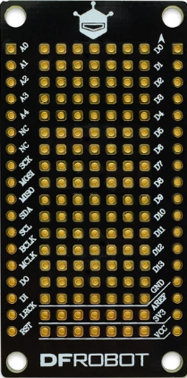
The Proto, commonly referred to as a breadboard, is a reusable prototyping platform designed for building and testing electronic circuits without the need for soldering. It features a grid of interconnected holes that allow components and wires to be easily inserted and removed, making it ideal for rapid prototyping and experimentation. The Proto is widely used in educational settings, hobbyist projects, and professional circuit design.
Explore Projects Built with Proto
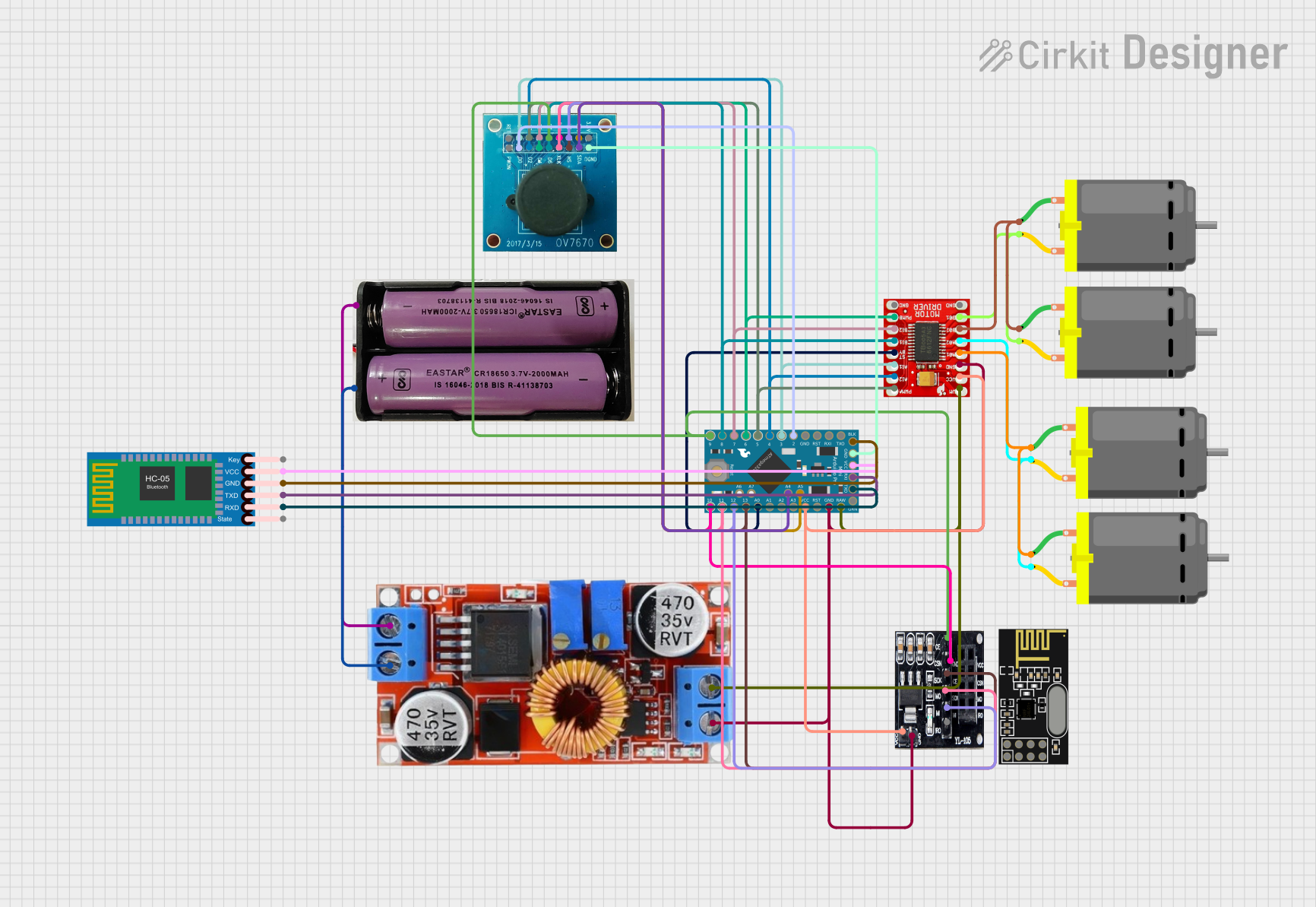
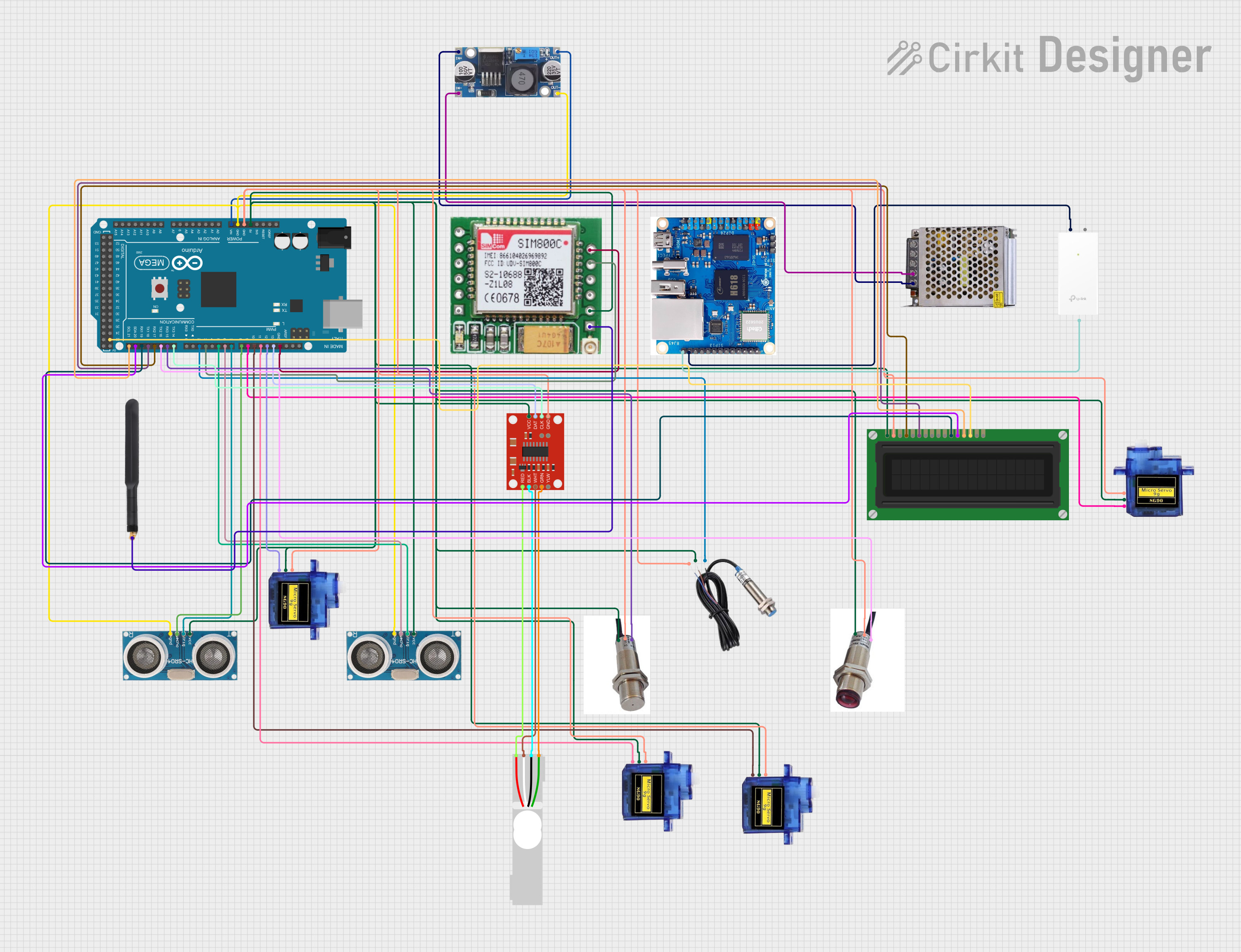
Explore Projects Built with Proto
Common Applications and Use Cases
- Rapid prototyping of electronic circuits
- Testing and debugging circuit designs
- Educational purposes for teaching electronics
- Temporary circuit assembly for proof-of-concept projects
- Experimenting with microcontroller-based systems (e.g., Arduino, Raspberry Pi)
Technical Specifications
- Material: ABS plastic housing with nickel-plated phosphor bronze contacts
- Dimensions: Typically 170mm x 55mm x 10mm (varies by model)
- Power Rails: Dual power rails for easy power distribution
- Terminal Strips: 630 tie-points (standard size)
- Voltage Rating: Up to 36V DC
- Current Rating: Up to 2A per contact
- Compatibility: Supports standard 22-28 AWG wires and most through-hole components
Pin Configuration and Descriptions
The Proto does not have traditional pins but instead features a grid of interconnected tie-points. Below is a description of the layout:
| Section | Description |
|---|---|
| Terminal Strips | Central area with rows of interconnected tie-points for component placement. |
| Power Rails | Horizontal rows on the top and bottom edges for power and ground connections. |
| Tie-Point Groups | Each row is divided into groups of 5 interconnected tie-points. |
Usage Instructions
How to Use the Proto in a Circuit
- Plan Your Circuit: Sketch the circuit diagram to determine the placement of components and connections.
- Insert Components: Place components (e.g., resistors, capacitors, ICs) into the terminal strip. Ensure that each leg of a component is in a separate tie-point group.
- Connect Wires: Use jumper wires to connect components and establish power and ground connections via the power rails.
- Power the Circuit: Connect a power source (e.g., battery, power supply) to the power rails. Ensure the voltage and current ratings are within the Proto's specifications.
- Test and Debug: Verify the circuit functionality and make adjustments as needed.
Important Considerations and Best Practices
- Avoid Overloading: Do not exceed the voltage and current ratings to prevent damage to the Proto or components.
- Use Proper Wire Gauge: Use 22-28 AWG wires for reliable connections.
- Check Connections: Ensure all connections are secure and free of shorts.
- Organize Wires: Use color-coded wires (e.g., red for power, black for ground) to simplify troubleshooting.
- Avoid Excessive Force: Insert and remove components gently to prevent damage to the tie-points.
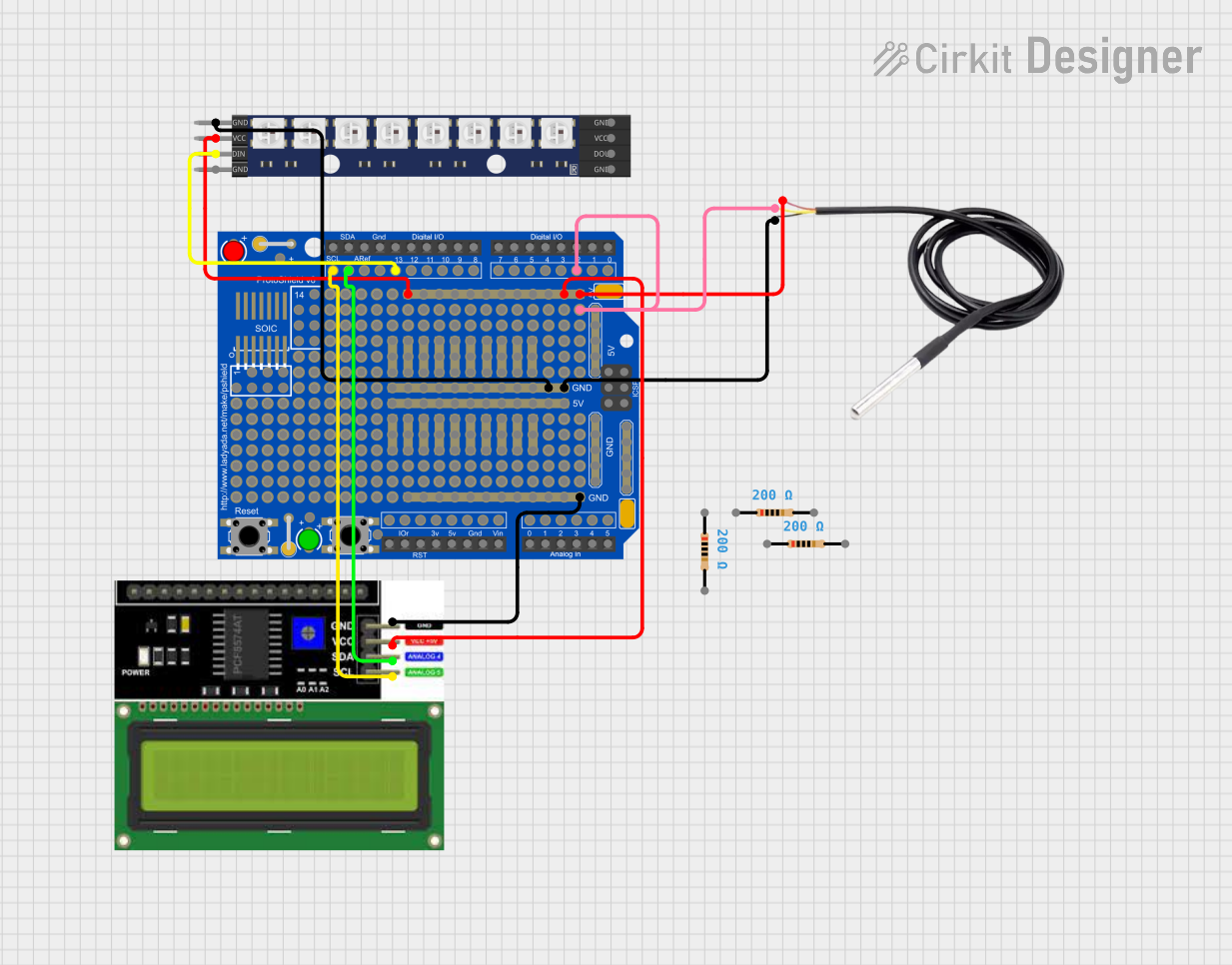
Example: Connecting an LED to an Arduino UNO
Below is an example of using the Proto to connect an LED to an Arduino UNO:
Circuit Diagram
- Connect the long leg (anode) of the LED to a 220-ohm resistor.
- Connect the other end of the resistor to pin 13 on the Arduino.
- Connect the short leg (cathode) of the LED to the ground rail on the Proto.
- Connect the ground rail to the Arduino's GND pin.
Arduino Code
// Simple LED Blink Example
// This code blinks an LED connected to pin 13 of the Arduino UNO.

void setup() {
  pinMode(13, OUTPUT); // Set pin 13 as an output
}

void loop() {
  digitalWrite(13, HIGH); // Turn the LED on
  delay(1000);            // Wait for 1 second
  digitalWrite(13, LOW);  // Turn the LED off
  delay(1000);            // Wait for 1 second
}
Troubleshooting and FAQs
Common Issues and Solutions
Loose Connections:
- Issue: Components or wires are not making proper contact.
- Solution: Ensure components and wires are fully inserted into the tie-points.
Short Circuits:
- Issue: Unintended connections between power and ground.
- Solution: Double-check the circuit layout and remove any misplaced wires.
Overheating Components:
- Issue: Components become excessively hot during operation.
- Solution: Verify that the voltage and current ratings of the components are not exceeded.
Power Rail Misuse:
- Issue: Incorrectly connecting power and ground to the same rail.
- Solution: Use separate rails for power (e.g., +5V) and ground (GND).
FAQs
Q: Can I use the Proto with high-frequency circuits?
- A: The Proto is not ideal for high-frequency circuits due to parasitic capacitance and inductance.
Q: How do I clean the Proto?
- A: Use a soft brush or compressed air to remove dust and debris. Avoid using liquids.
Q: Can I solder components to the Proto?
- A: No, the Proto is designed for solderless prototyping. Use a PCB for permanent circuits.
Q: What is the maximum wire size I can use?
- A: The Proto supports wires in the range of 22-28 AWG.