How to Use M5StickS3: Examples, Pinouts, and Specs
Introduction
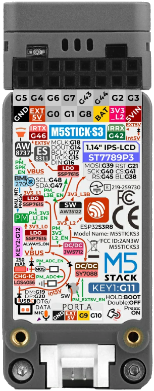
The M5StickS3 is a compact and portable development board manufactured by M5Stack. It is powered by the ESP32-S3 microcontroller, which features dual-core processing, Wi-Fi, and Bluetooth connectivity. The M5StickS3 is designed for Internet of Things (IoT) applications and is equipped with a built-in display, multiple sensors, and GPIO pins for interfacing with external components. Its small form factor and versatile features make it ideal for prototyping, wearable devices, and embedded systems.
Explore Projects Built with M5StickS3


Explore Projects Built with M5StickS3
Common Applications and Use Cases
- IoT device prototyping
- Wearable technology
- Environmental monitoring
- Smart home automation
- Educational projects and STEM learning
- Portable data logging and visualization
Technical Specifications
The M5StickS3 is packed with features that make it a powerful and versatile development board. Below are its key technical specifications:
General Specifications
| Feature | Specification |
|---|---|
| Microcontroller | ESP32-S3 (Xtensa® 32-bit LX7 dual-core processor) |
| Wireless Connectivity | Wi-Fi 802.11 b/g/n, Bluetooth 5.0 LE |
| Display | 0.96-inch TFT LCD, 160x80 resolution |
| Flash Memory | 16 MB |
| PSRAM | 8 MB |
| Power Supply | 5V via USB-C or 3.7V LiPo battery |
| Battery | Built-in 80mAh LiPo rechargeable battery |
| Dimensions | 48.2mm x 25.5mm x 14.2mm |
Pin Configuration and Descriptions
The M5StickS3 features a GPIO header for interfacing with external components. Below is the pin configuration:
| Pin Name | Function | Description |
|---|---|---|
| GND | Ground | Common ground for the circuit |
| 5V | Power Input | 5V power supply input |
| 3V3 | Power Output | 3.3V power output |
| GPIO0 | General Purpose I/O | Configurable digital/analog pin |
| GPIO1 | General Purpose I/O | Configurable digital/analog pin |
| GPIO2 | General Purpose I/O | Configurable digital/analog pin |
| SDA | I2C Data Line | Data line for I2C communication |
| SCL | I2C Clock Line | Clock line for I2C communication |
Usage Instructions
The M5StickS3 is easy to use and can be programmed using popular development environments such as Arduino IDE, MicroPython, or ESP-IDF. Below are the steps to get started:
Setting Up the M5StickS3
- Install Drivers: Ensure that the necessary USB drivers for the ESP32-S3 are installed on your computer.
- Download Development Environment: Install the Arduino IDE or another compatible IDE.
- Install ESP32 Board Package:
- Open the Arduino IDE.
- Go to
File > Preferencesand add the following URL to the "Additional Board Manager URLs" field:https://dl.espressif.com/dl/package_esp32_index.json - Go to
Tools > Board > Boards Manager, search for "ESP32," and install the package.
- Connect the M5StickS3: Use a USB-C cable to connect the board to your computer.
Example Code: Displaying Text on the Screen
The following Arduino code demonstrates how to display text on the M5StickS3's built-in screen:
#include <M5StickCPlus.h> // Include the M5Stick library

void setup() {
  M5.begin(); // Initialize the M5StickS3
  M5.Lcd.setRotation(1); // Set screen orientation
  M5.Lcd.fillScreen(BLACK); // Clear the screen with a black background
  M5.Lcd.setTextColor(WHITE); // Set text color to white
  M5.Lcd.setTextSize(2); // Set text size
  M5.Lcd.setCursor(10, 10); // Set cursor position
  M5.Lcd.print("Hello, M5StickS3!"); // Display text on the screen
}

void loop() {
  // No actions in the loop for this example
}
Important Considerations and Best Practices
- Power Supply: Use a reliable 5V USB power source or ensure the built-in battery is charged.
- GPIO Voltage Levels: The GPIO pins operate at 3.3V. Avoid applying higher voltages to prevent damage.
- Heat Management: The ESP32-S3 may generate heat during operation. Ensure proper ventilation if used in an enclosure.
- Firmware Updates: Regularly check for firmware updates from M5Stack to ensure optimal performance.
Troubleshooting and FAQs
Common Issues and Solutions
The board is not detected by the computer:
- Ensure the USB-C cable supports data transfer (not just charging).
- Verify that the correct USB drivers are installed.
- Try a different USB port or cable.
The screen does not display anything:
- Check the power supply and ensure the board is powered on.
- Verify that the code is correctly uploaded and includes the
M5.begin()initialization.
Wi-Fi or Bluetooth is not working:
- Ensure the correct credentials are provided in the code for Wi-Fi.
- Check that the ESP32-S3 firmware is up to date.
The board overheats:
- Avoid running high-power tasks for extended periods.
- Use a heatsink or ensure proper ventilation.
FAQs
Q: Can I use the M5StickS3 with MicroPython?
A: Yes, the M5StickS3 supports MicroPython. You can flash the MicroPython firmware and use the mpy libraries provided by M5Stack.
Q: What is the battery life of the M5StickS3?
A: The built-in 80mAh battery provides limited runtime, depending on the application. For extended use, connect an external power source.
Q: Can I connect external sensors to the M5StickS3?
A: Yes, the GPIO pins and I2C interface allow you to connect a variety of external sensors and modules.
Q: Is the M5StickS3 compatible with Arduino libraries?
A: Yes, the M5StickS3 is compatible with most Arduino libraries, especially those designed for the ESP32 platform.