How to Use Keypad: Examples, Pinouts, and Specs
Introduction
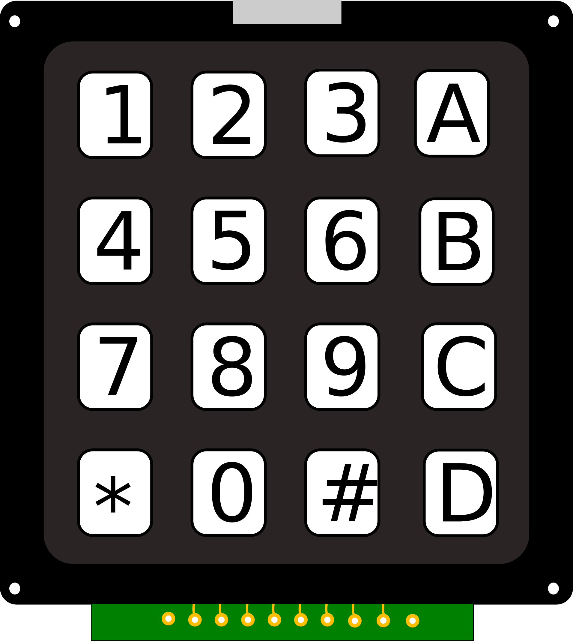
A keypad is an input device consisting of a set of keys or buttons that allow users to enter data or commands into a system. It is commonly used in electronic devices for user interaction, such as security systems, calculators, vending machines, and access control systems. Keypads are available in various configurations, including 3x4 (12 keys) and 4x4 (16 keys), and are typically interfaced with microcontrollers or other digital systems.
Explore Projects Built with Keypad

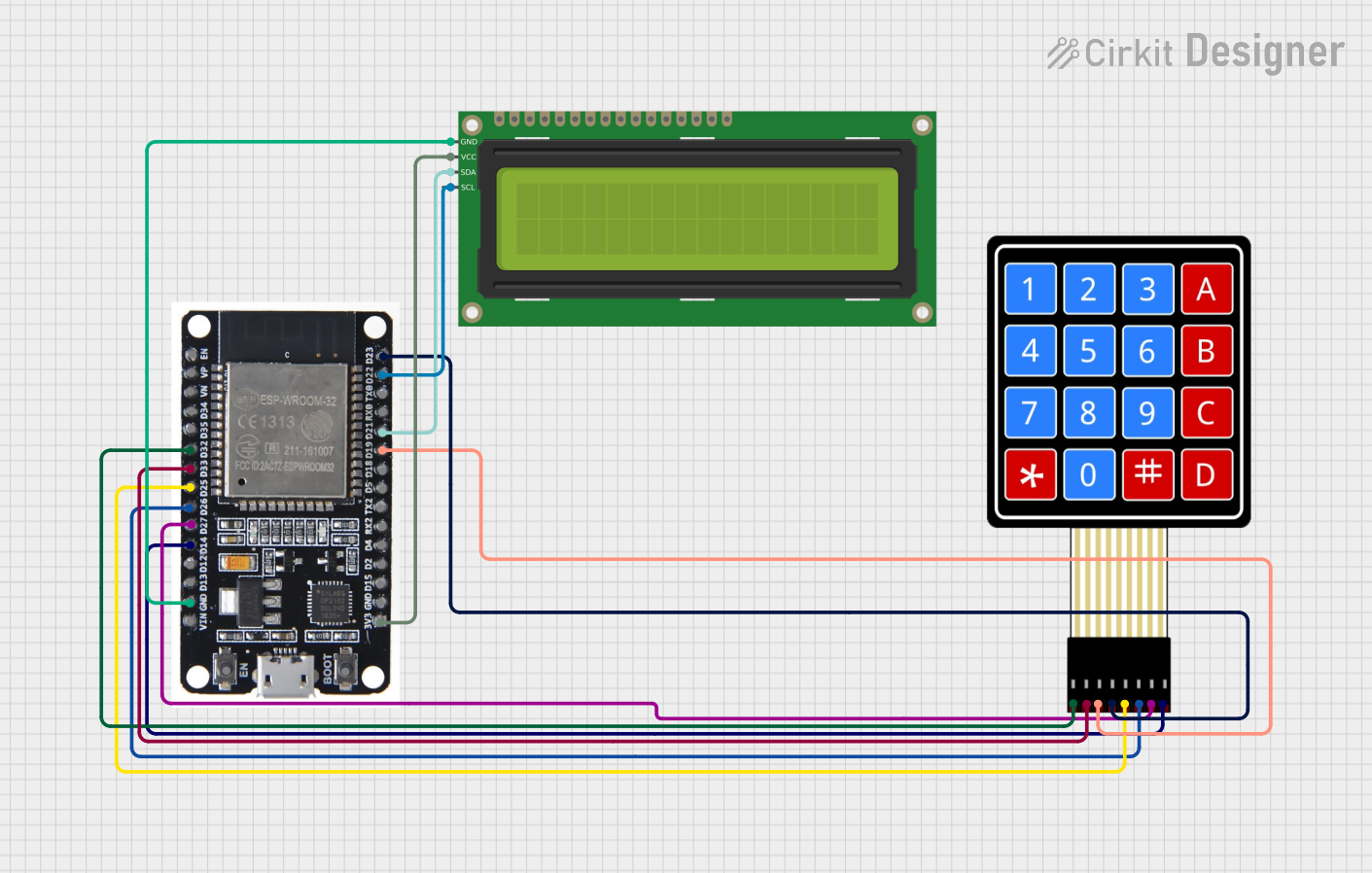
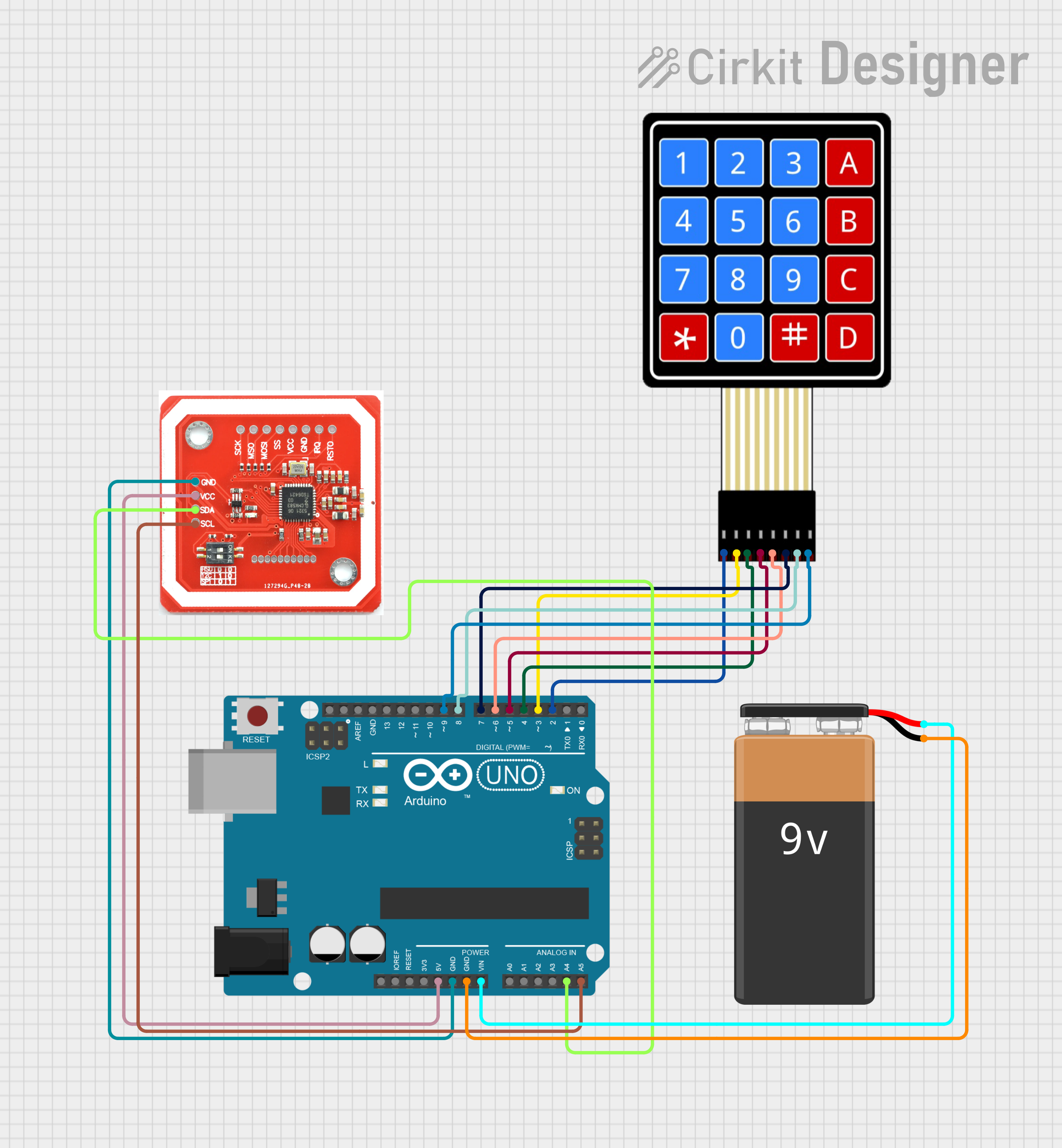

Explore Projects Built with Keypad
Common Applications and Use Cases
- Security systems (e.g., PIN entry for door locks)
- User interfaces for embedded systems
- Calculators and vending machines
- Home automation systems
- Menu navigation in electronic devices
Technical Specifications
Keypads are passive devices that consist of a matrix of rows and columns. When a key is pressed, it connects a specific row and column, allowing the microcontroller to detect the keypress.
General Specifications
- Operating Voltage: 3.3V to 5V
- Key Configurations: 3x4 (12 keys) or 4x4 (16 keys)
- Interface: Matrix of rows and columns
- Material: Plastic or rubber keys with conductive pads
- Debouncing: Requires software or hardware debouncing
Pin Configuration and Descriptions
Below is the pin configuration for a standard 4x4 keypad:
| Pin Number | Pin Name | Description |
|---|---|---|
| 1 | R1 | Row 1 |
| 2 | R2 | Row 2 |
| 3 | R3 | Row 3 |
| 4 | R4 | Row 4 |
| 5 | C1 | Column 1 |
| 6 | C2 | Column 2 |
| 7 | C3 | Column 3 |
| 8 | C4 | Column 4 |
For a 3x4 keypad, the configuration is similar, but it has 3 columns (C1, C2, C3) and 4 rows (R1, R2, R3, R4).
Usage Instructions
How to Use the Keypad in a Circuit
Connect the Keypad to a Microcontroller:
- Connect the row pins (R1 to R4) and column pins (C1 to C4) to the GPIO pins of the microcontroller.
- Use pull-up or pull-down resistors if required by your microcontroller.
Install a Keypad Library:
- For Arduino, use the
Keypadlibrary, which simplifies interfacing with the keypad.
- For Arduino, use the
Write Code to Detect Keypresses:
- Scan the rows and columns to detect which key is pressed.
- Use software debouncing to ensure reliable keypress detection.
Important Considerations and Best Practices
- Debouncing: Keypads may produce multiple signals for a single press due to mechanical bouncing. Use software or hardware debouncing to filter out these signals.
- Pull-up/Pull-down Resistors: Ensure proper pull-up or pull-down resistors are used to avoid floating inputs.
- Voltage Compatibility: Verify that the keypad's operating voltage matches the microcontroller's input voltage levels.
- Keypad Layout: Confirm the key layout (e.g., 3x4 or 4x4) matches your application.
Example Code for Arduino UNO
Below is an example of how to use a 4x4 keypad with an Arduino UNO:
#include <Keypad.h>

// Define the rows and columns of the keypad
const byte ROWS = 4; // Number of rows
const byte COLS = 4; // Number of columns

// Define the keymap for the keypad
char keys[ROWS][COLS] = {
  {'1', '2', '3', 'A'},
  {'4', '5', '6', 'B'},
  {'7', '8', '9', 'C'},
  {'*', '0', '#', 'D'}
};

// Define the row and column pins connected to the Arduino
byte rowPins[ROWS] = {9, 8, 7, 6};   // Connect to R1, R2, R3, R4
byte colPins[COLS] = {5, 4, 3, 2};   // Connect to C1, C2, C3, C4

// Create a Keypad object
Keypad keypad = Keypad(makeKeymap(keys), rowPins, colPins, ROWS, COLS);

void setup() {
  Serial.begin(9600); // Initialize serial communication
  Serial.println("Keypad Test: Press a key");
}

void loop() {
  char key = keypad.getKey(); // Get the key pressed

  if (key) { // If a key is pressed
    Serial.print("Key Pressed: ");
    Serial.println(key); // Print the key to the serial monitor
  }
}
Notes:
- Replace the
rowPinsandcolPinsarrays with the actual GPIO pins you are using. - Open the Arduino Serial Monitor to view the keypresses.
Troubleshooting and FAQs
Common Issues and Solutions
No Keypress Detected:
- Ensure the keypad is properly connected to the microcontroller.
- Verify the pin configuration in the code matches the hardware connections.
Incorrect Key Detected:
- Check the keymap in the code to ensure it matches the physical layout of the keypad.
- Verify that the row and column pins are correctly assigned.
Multiple Keypresses Detected:
- Implement software debouncing to filter out mechanical bouncing.
- Ensure the keypad is not damaged or worn out.
Floating Inputs:
- Use pull-up or pull-down resistors to stabilize the input signals.
FAQs
Q: Can I use a 3x4 keypad with the same code?
A: Yes, but you need to adjust the ROWS, COLS, keys, rowPins, and colPins variables in the code to match the 3x4 configuration.
Q: How do I extend the keypad cable length?
A: Use shielded cables to reduce noise and interference. Avoid excessively long cables to prevent signal degradation.
Q: Can I use the keypad with a 3.3V microcontroller?
A: Yes, as long as the keypad operates within the 3.3V range. Verify compatibility in the technical specifications.
Q: How do I handle multiple simultaneous keypresses?
A: Most keypads do not support multi-key detection. Use a custom keypad or advanced scanning techniques if this feature is required.