
How to Use Basic FET P-Channel: Examples, Pinouts, and Specs
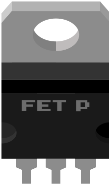
 Design with Basic FET P-Channel in Cirkit Designer
Introduction
- The Basic FET P-Channel is a type of Field Effect Transistor (FET) that enables current to flow from the source to the drain when a negative voltage is applied to the gate terminal.
- This component is widely used in electronic circuits for switching and signal amplification due to its high efficiency and low power consumption.
- Common applications include:
- Load switching in power management circuits
- Signal amplification in analog circuits
- Reverse polarity protection
- Motor control and LED dimming
Explore Projects Built with Basic FET P-Channel
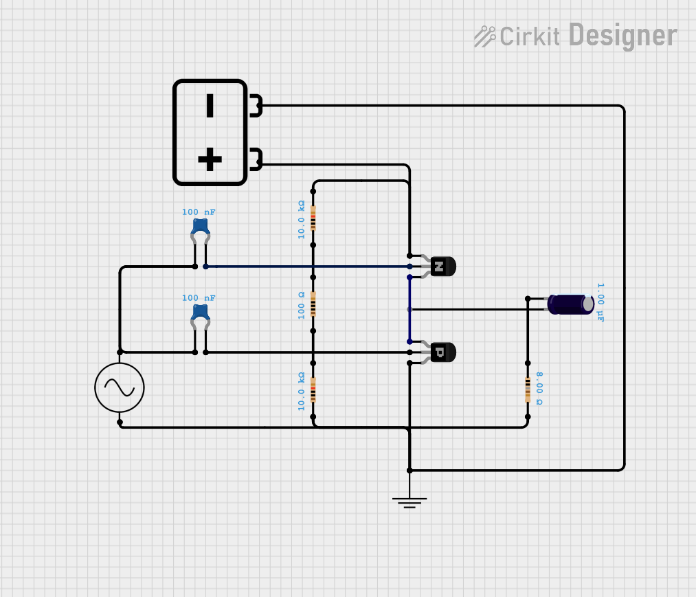 Open Project in Cirkit Designer
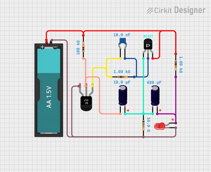 Open Project in Cirkit Designer
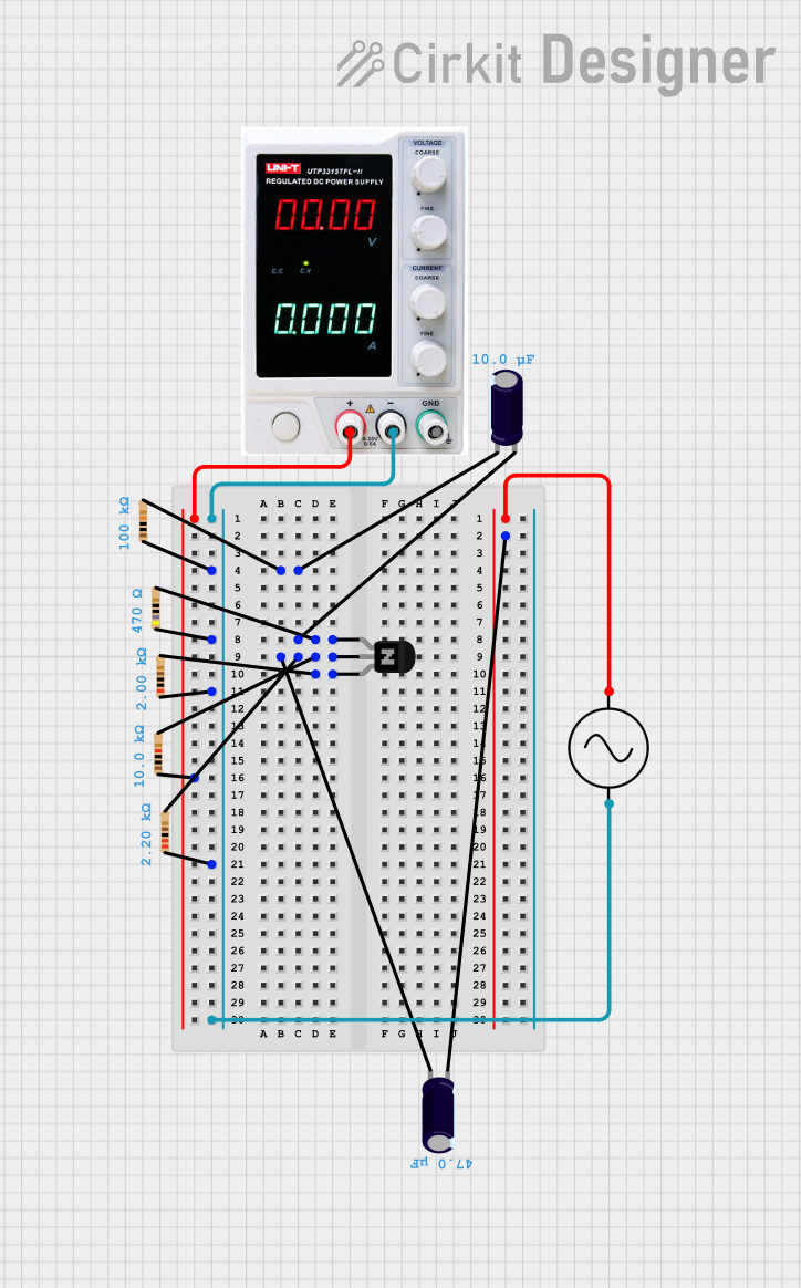 Open Project in Cirkit Designer
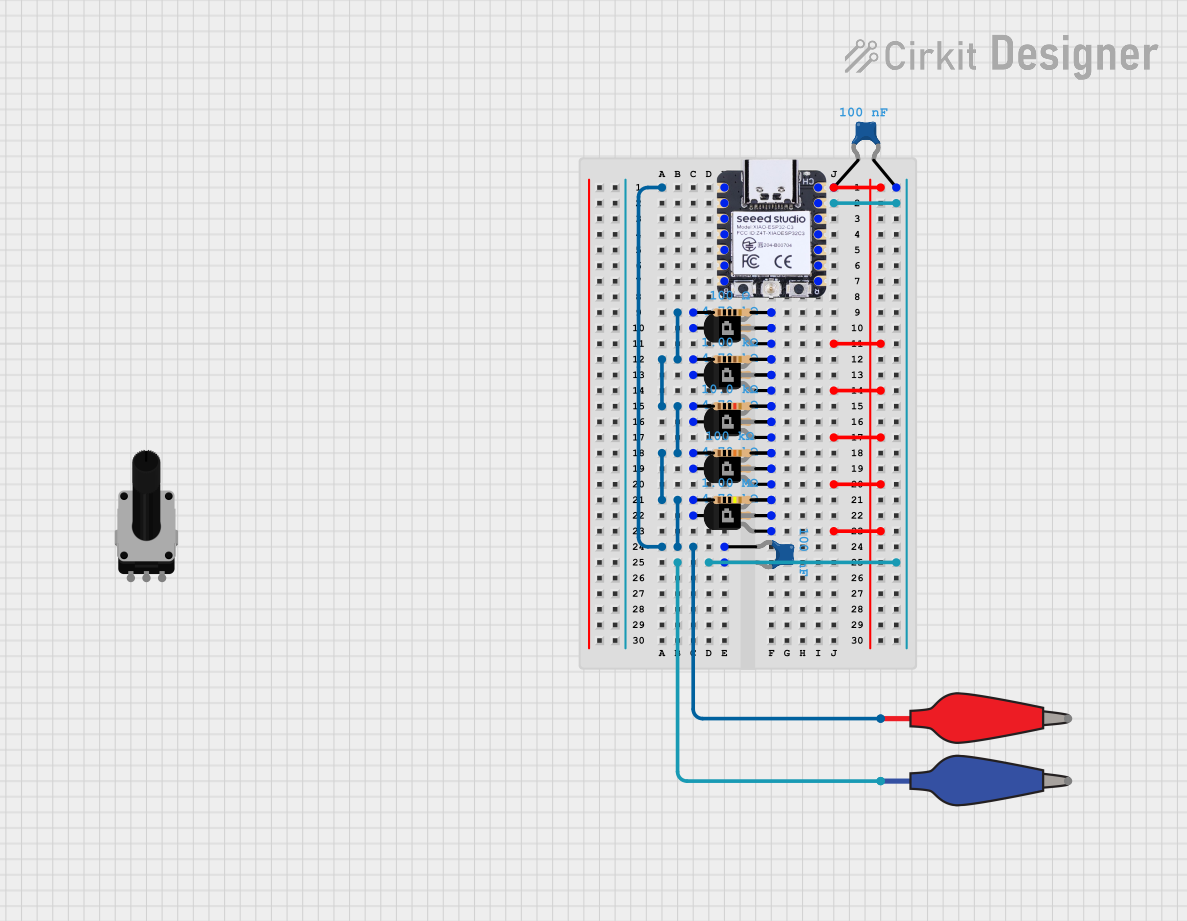 Open Project in Cirkit Designer
Explore Projects Built with Basic FET P-Channel
Open Project in Cirkit DesignerOpen Project in Cirkit DesignerOpen Project in Cirkit DesignerOpen Project in Cirkit DesignerTechnical Specifications
- Type: P-Channel MOSFET
- Voltage Ratings:
- Maximum Drain-Source Voltage (VDS): -30V to -100V (varies by model)
- Gate-Source Threshold Voltage (VGS(th)): -2V to -4V
- Current Ratings:
- Maximum Drain Current (ID): -1A to -10A (varies by model)
- Power Dissipation: Typically 1W to 3W
- RDS(on) (On-Resistance): 0.1Ω to 1Ω
- Package Types: TO-220, TO-92, SOT-23, etc.
Pin Configuration and Descriptions
Below is the pin configuration for a typical P-Channel MOSFET in a TO-220 package:
| Pin Number | Pin Name | Description |
|---|---|---|
| 1 | Gate | Controls the flow of current between the |
| source and drain. A negative voltage is | ||
| applied here to turn the FET on. | ||
| 2 | Drain | Current flows out of this terminal when |
| the FET is on. | ||
| 3 | Source | Current flows into this terminal. |
| Tab | Drain | The metal tab is internally connected to |
| the drain terminal for heat dissipation. |
Usage Instructions
How to Use the Basic FET P-Channel in a Circuit
Connecting the Terminals:
- Connect the source terminal to the positive voltage supply (VCC).
- Connect the drain terminal to the load (e.g., a motor or LED).
- Apply a negative voltage to the gate terminal relative to the source to turn the FET on.
Gate Resistor:
- Use a resistor (typically 10kΩ to 100kΩ) between the gate and source to prevent floating gate voltage, which can cause erratic behavior.
Protection Diode:
- For inductive loads (e.g., motors), add a flyback diode across the load to protect the FET from voltage spikes.
Driving the Gate:
- Ensure the gate voltage (VGS) is sufficiently negative to fully turn on the FET. For example, if the threshold voltage is -3V, apply at least -5V to the gate.
Example Circuit with Arduino UNO
Below is an example of using a Basic FET P-Channel to control an LED with an Arduino UNO:
// Define the pin connected to the gate of the P-Channel FET
const int gatePin = 9;

void setup() {
  pinMode(gatePin, OUTPUT); // Set the gate pin as an output
  digitalWrite(gatePin, HIGH); // Turn off the FET (gate voltage = source voltage)
}

void loop() {
  // Turn on the FET (apply negative voltage to the gate)
  digitalWrite(gatePin, LOW);
  delay(1000); // Keep the LED on for 1 second

  // Turn off the FET (gate voltage = source voltage)
  digitalWrite(gatePin, HIGH);
  delay(1000); // Keep the LED off for 1 second
}
Note: In this example, the source terminal of the FET is connected to the positive voltage supply (e.g., 5V), and the drain terminal is connected to the LED and a current-limiting resistor.
Important Considerations and Best Practices
- Heat Dissipation: Use a heatsink if the FET is handling high currents to prevent overheating.
- Voltage Ratings: Ensure the applied voltages do not exceed the maximum ratings to avoid damaging the FET.
- Gate Drive Voltage: Use a gate driver circuit if the microcontroller cannot provide sufficient voltage to fully turn on the FET.
Troubleshooting and FAQs
Common Issues
FET Not Turning On:
- Check if the gate voltage is sufficiently negative relative to the source.
- Verify the gate resistor value is appropriate (not too high or too low).
Excessive Heat:
- Ensure the FET is operating within its current and power dissipation limits.
- Add a heatsink or improve ventilation if necessary.
Load Not Functioning:
- Verify the connections to the source, drain, and load.
- Check if the load requires more current than the FET can handle.
FAQs
Q: Can I use a P-Channel FET with a 3.3V microcontroller?
A: Yes, but ensure the gate voltage is sufficiently negative relative to the source. You may need a level shifter or gate driver circuit.
Q: Why is my FET always on?
A: This could be due to a floating gate. Add a pull-up resistor between the gate and source to ensure the gate voltage is properly controlled.
Q: Can I use a P-Channel FET for high-side switching?
A: Yes, P-Channel FETs are ideal for high-side switching applications. Ensure the source is connected to the positive voltage supply and the gate voltage is properly controlled.