How to Use Rocker Switch (SPST): Examples, Pinouts, and Specs
Introduction
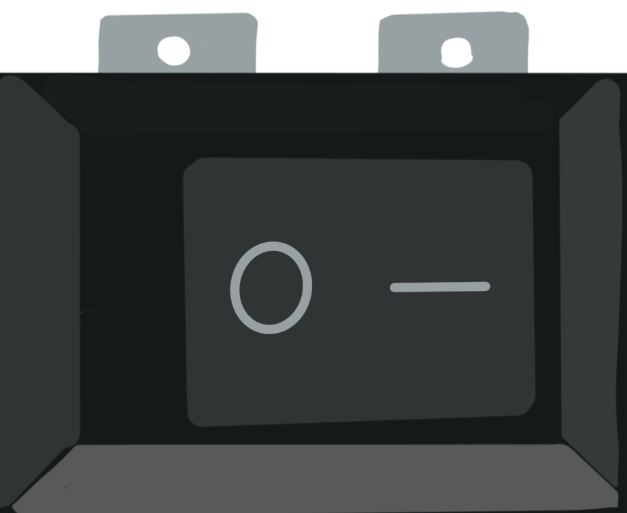
A Rocker Switch (Single Pole Single Throw), manufactured by Switch Electronics, is a simple yet versatile electrical switch designed to toggle between two positions: ON and OFF. This switch allows or interrupts the flow of current in a circuit, making it an essential component for power control in various applications. Its intuitive design and reliability make it a popular choice for both household appliances and electronic devices.
Explore Projects Built with Rocker Switch (SPST)

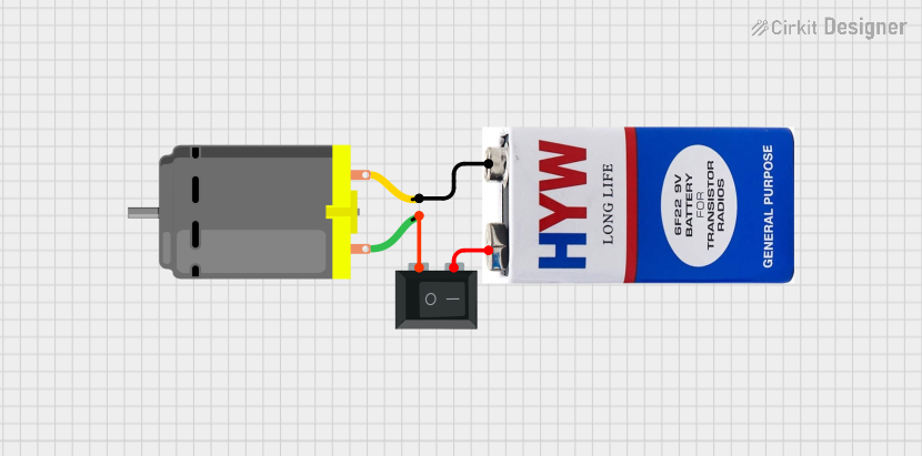
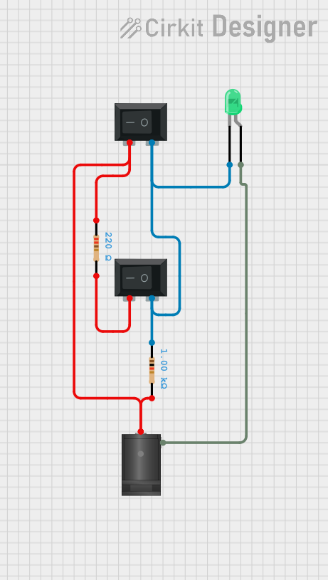

Explore Projects Built with Rocker Switch (SPST)
Common Applications and Use Cases
- Power control in household appliances (e.g., lamps, fans, and kitchen devices)
- On/Off control in electronic projects and DIY circuits
- Automotive applications for auxiliary devices
- Industrial equipment for basic power switching
Technical Specifications
Below are the key technical details for the Rocker Switch (SPST):
| Parameter | Value |
|---|---|
| Manufacturer | Switch Electronics |
| Manufacturer Part ID | N/A |
| Switch Type | Single Pole Single Throw (SPST) |
| Rated Voltage | 250V AC |
| Rated Current | 6A |
| Contact Resistance | ≤ 50 mΩ |
| Insulation Resistance | ≥ 100 MΩ |
| Operating Temperature | -25°C to +85°C |
| Mechanical Life | 10,000 cycles |
| Mounting Type | Panel Mount |
| Actuator Type | Rocker |
Pin Configuration and Descriptions
The Rocker Switch (SPST) typically has two terminals for connection. Below is the pin configuration:
| Pin | Description |
|---|---|
| Pin 1 | Input terminal: Connect to the power source |
| Pin 2 | Output terminal: Connect to the load or circuit |
Usage Instructions
How to Use the Component in a Circuit
- Identify the Terminals: Locate the two terminals on the switch. Pin 1 is for the input (power source), and Pin 2 is for the output (load or circuit).
- Prepare the Circuit: Ensure the circuit is powered off before connecting the switch to avoid electrical hazards.
- Connect the Switch:
- Connect Pin 1 to the positive terminal of the power source.
- Connect Pin 2 to the positive terminal of the load or circuit.
- Complete the circuit by connecting the negative terminal of the load back to the power source.
- Mount the Switch: Secure the switch in a panel or enclosure using the provided mounting mechanism.
- Test the Circuit: Power on the circuit and toggle the switch to verify its operation.
Important Considerations and Best Practices
- Voltage and Current Ratings: Ensure the switch is used within its rated voltage (250V AC) and current (6A) to prevent damage or failure.
- Proper Mounting: Use the appropriate panel cutout dimensions to securely mount the switch.
- Debouncing: If used in a digital circuit, consider implementing debouncing techniques to avoid false triggering.
- Safety Precautions: Always disconnect the power supply before wiring or modifying the circuit.
Example: Connecting to an Arduino UNO
While the Rocker Switch (SPST) is primarily a power control device, it can also be used as a digital input for microcontroller projects. Below is an example of connecting the switch to an Arduino UNO:
Circuit Setup
- Connect Pin 1 of the switch to the 5V pin on the Arduino.
- Connect Pin 2 of the switch to a digital input pin (e.g., D2) on the Arduino.
- Add a pull-down resistor (10kΩ) between Pin 2 and GND to ensure a stable LOW state when the switch is OFF.
Arduino Code
// Rocker Switch (SPST) Example with Arduino UNO
// This code reads the state of the switch and turns on an LED when the switch is ON.

const int switchPin = 2;  // Pin connected to the switch
const int ledPin = 13;    // Pin connected to the onboard LED

void setup() {
  pinMode(switchPin, INPUT);  // Set the switch pin as input
  pinMode(ledPin, OUTPUT);    // Set the LED pin as output
  digitalWrite(ledPin, LOW);  // Ensure the LED is off initially
}

void loop() {
  int switchState = digitalRead(switchPin);  // Read the switch state

  if (switchState == HIGH) {
    // If the switch is ON, turn on the LED
    digitalWrite(ledPin, HIGH);
  } else {
    // If the switch is OFF, turn off the LED
    digitalWrite(ledPin, LOW);
  }
}
Troubleshooting and FAQs
Common Issues and Solutions
Switch Not Working:
- Cause: Loose or incorrect wiring.
- Solution: Double-check the connections and ensure the terminals are properly secured.
Switch Feels Stiff or Jammed:
- Cause: Dirt or debris inside the switch mechanism.
- Solution: Clean the switch carefully or replace it if necessary.
Load Not Receiving Power:
- Cause: Exceeding the switch's rated current or voltage.
- Solution: Verify the load's power requirements and ensure they are within the switch's ratings.
Arduino Not Detecting Switch State:
- Cause: Missing pull-down resistor or incorrect pin configuration.
- Solution: Add a pull-down resistor and confirm the correct pin connections.
FAQs
Q1: Can this switch be used for DC circuits?
A1: Yes, the Rocker Switch (SPST) can be used for DC circuits, but ensure the voltage and current ratings are not exceeded.
Q2: Is the switch waterproof?
A2: No, this switch is not waterproof. For outdoor or wet environments, use a waterproof variant.
Q3: Can I use this switch to control multiple devices?
A3: No, this is a Single Pole Single Throw (SPST) switch, which can control only one circuit at a time. For multiple devices, consider using a multi-pole switch.
Q4: How do I debounce the switch in a digital circuit?
A4: You can use a hardware debounce circuit (e.g., capacitor and resistor) or implement software debouncing in your microcontroller code.