How to Use ESP32: Examples, Pinouts, and Specs
Introduction
The ESP32 is a low-cost, low-power system on a chip (SoC) developed by Espressif Systems. It features integrated Wi-Fi and Bluetooth capabilities, making it an ideal choice for Internet of Things (IoT) applications, smart devices, and embedded systems. The ESP32 is highly versatile, offering dual-core processing, a wide range of GPIO pins, and support for various communication protocols.
Explore Projects Built with ESP32


Explore Projects Built with ESP32
Common Applications and Use Cases
- IoT devices (e.g., smart home systems, sensors, and actuators)
- Wearable technology
- Wireless communication hubs
- Robotics and automation
- Data logging and remote monitoring
- Prototyping and development of connected devices
Technical Specifications
The ESP32 is packed with features that make it a powerful and flexible component for a wide range of applications. Below are its key technical specifications:
Key Technical Details
- Processor: Dual-core Xtensa® 32-bit LX6 microprocessor, up to 240 MHz
- Memory: 520 KB SRAM, 4 MB Flash (varies by model)
- Wi-Fi: 802.11 b/g/n, 2.4 GHz
- Bluetooth: v4.2 BR/EDR and BLE
- Operating Voltage: 3.0V to 3.6V
- GPIO Pins: 34 (multipurpose, including ADC, DAC, PWM, I2C, SPI, UART)
- ADC Channels: 18 (12-bit resolution)
- DAC Channels: 2 (8-bit resolution)
- Power Consumption: Ultra-low power in deep sleep mode (~10 µA)
- Operating Temperature: -40°C to 125°C
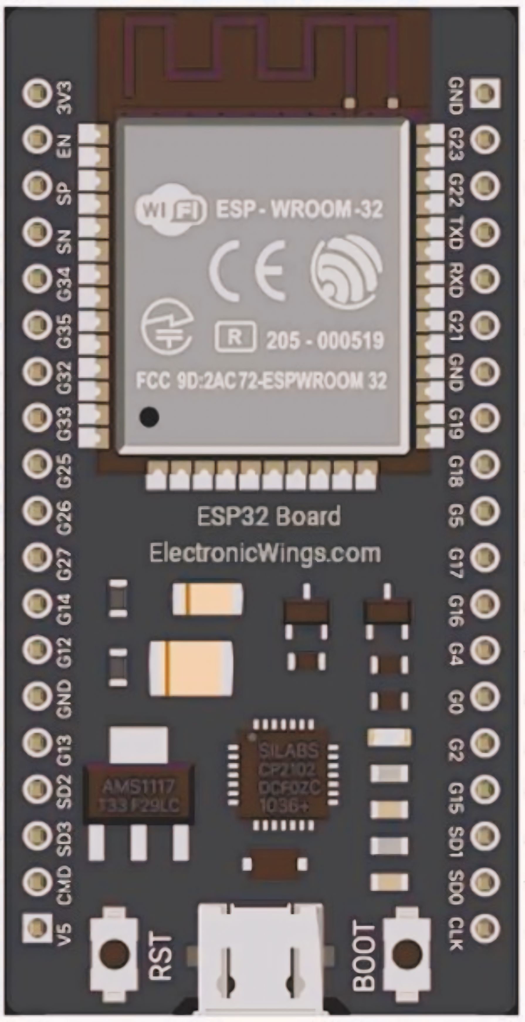
Pin Configuration and Descriptions
The ESP32 has a variety of pins for different functionalities. Below is a table summarizing the key pins and their descriptions:
| Pin Name | Function | Description |
|---|---|---|
| GPIO0 | Input/Output, Boot Mode Selection | Used for general I/O or to select boot mode during startup. |
| GPIO2 | Input/Output, ADC, DAC | General-purpose I/O, supports ADC and DAC functionality. |
| GPIO12 | Input/Output, ADC, Touch Sensor | General-purpose I/O, supports ADC and capacitive touch sensing. |
| GPIO15 | Input/Output, PWM, UART | General-purpose I/O, supports PWM and UART communication. |
| EN | Enable | Active-high pin to enable or reset the chip. |
| 3V3 | Power | Provides 3.3V power to the ESP32. |
| GND | Ground | Ground connection. |
| TX0 (GPIO1) | UART Transmit | UART0 transmit pin for serial communication. |
| RX0 (GPIO3) | UART Receive | UART0 receive pin for serial communication. |
| VIN | Power Input | Accepts input voltage (5V) to power the ESP32 via onboard voltage regulator. |
Note: The exact pinout may vary depending on the ESP32 module or development board (e.g., ESP32-WROOM-32, ESP32-DevKitC).
Usage Instructions
The ESP32 can be used in a variety of circuits and projects. Below are the steps to get started and some best practices to follow.
How to Use the ESP32 in a Circuit
Powering the ESP32:
- Connect the VIN pin to a 5V power source or use the 3V3 pin for a regulated 3.3V supply.
- Ensure the GND pin is connected to the ground of your circuit.
Programming the ESP32:
- Use a USB-to-serial adapter or a development board with a built-in USB interface.
- Install the ESP32 board package in the Arduino IDE or use the Espressif IDF (IoT Development Framework) for advanced development.
- Select the correct board and port in the IDE before uploading code.
Connecting Peripherals:
- Use GPIO pins for connecting sensors, actuators, or other peripherals.
- Configure the pins in your code according to the required functionality (e.g., input, output, ADC).
Wi-Fi and Bluetooth Setup:
- Use the built-in libraries (e.g.,
WiFi.handBluetoothSerial.hin Arduino IDE) to configure wireless communication.
- Use the built-in libraries (e.g.,
Example Code for Arduino IDE
Below is an example of how to connect the ESP32 to a Wi-Fi network and print the IP address:
#include <WiFi.h> // Include the Wi-Fi library

const char* ssid = "Your_SSID";       // Replace with your Wi-Fi network name
const char* password = "Your_Password"; // Replace with your Wi-Fi password

void setup() {
  Serial.begin(115200); // Initialize serial communication at 115200 baud
  delay(1000);

  Serial.println("Connecting to Wi-Fi...");
  WiFi.begin(ssid, password); // Start Wi-Fi connection

  while (WiFi.status() != WL_CONNECTED) {
    delay(500);
    Serial.print("."); // Print dots while connecting
  }

  Serial.println("\nWi-Fi connected!");
  Serial.print("IP Address: ");
  Serial.println(WiFi.localIP()); // Print the assigned IP address
}

void loop() {
  // Add your main code here
}
Important Considerations and Best Practices
- Voltage Levels: Ensure all connected peripherals operate at 3.3V logic levels to avoid damaging the ESP32.
- Power Supply: Use a stable power source to prevent unexpected resets or instability.
- Deep Sleep Mode: Utilize the deep sleep mode for battery-powered applications to conserve energy.
- Pin Multiplexing: Be aware that some pins have multiple functions. Check the datasheet to avoid conflicts.
Troubleshooting and FAQs
Common Issues and Solutions
ESP32 Not Connecting to Wi-Fi:
- Solution: Double-check the SSID and password. Ensure the router is within range and supports 2.4 GHz Wi-Fi.
Serial Monitor Not Displaying Output:
- Solution: Verify the correct COM port and baud rate (115200 by default) in the Arduino IDE.
ESP32 Keeps Resetting:
- Solution: Check the power supply for stability. Ensure the ESP32 is not drawing more current than the source can provide.
GPIO Pins Not Working as Expected:
- Solution: Confirm the pin configuration in your code. Avoid using pins reserved for specific functions (e.g., GPIO6-GPIO11 for flash memory).
FAQs
Q: Can the ESP32 operate on 5V logic?
A: No, the ESP32 operates on 3.3V logic. Use level shifters if interfacing with 5V devices.
Q: How do I update the ESP32 firmware?
A: Use the Espressif Flash Download Tool or the Arduino IDE to upload new firmware.
Q: Can I use the ESP32 with batteries?
A: Yes, the ESP32 can be powered by batteries. Use a voltage regulator or a LiPo battery with a 3.3V output.
Q: What is the maximum range of the ESP32's Wi-Fi?
A: The range depends on the environment but typically extends up to 100 meters in open spaces.
By following this documentation, you can effectively integrate the ESP32 into your projects and troubleshoot common issues.