How to Use ADUM-1201: Examples, Pinouts, and Specs
Introduction
The ADUM-1201 is a digital isolator designed to provide galvanic isolation between two circuits. It ensures safe data transmission by electrically isolating the input and output sides, preventing high voltages or noise from affecting sensitive low-voltage circuits. This component is based on Analog Devices' iCoupler® technology, which uses micro-transformers to achieve high-speed, reliable isolation.
Explore Projects Built with ADUM-1201


Explore Projects Built with ADUM-1201
Common Applications and Use Cases
- Industrial automation and control systems
- Medical equipment requiring isolation for patient safety
- Power supply and motor control systems
- Communication interfaces in high-voltage environments
- Signal integrity enhancement in noisy environments
Technical Specifications
Key Technical Details
| Parameter | Value |
|---|---|
| Isolation Voltage | 2.5 kV RMS |
| Data Rate | Up to 25 Mbps |
| Supply Voltage (VDD1/VDD2) | 2.7 V to 5.5 V |
| Propagation Delay | 50 ns (typical) |
| Common-Mode Transient | >25 kV/µs |
| Operating Temperature | -40°C to +125°C |
| Channels | 2 (unidirectional or bidirectional) |
| Package | 8-lead SOIC (Small Outline Integrated Circuit) |
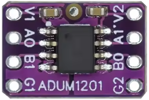
Pin Configuration and Descriptions
The ADUM-1201 is available in an 8-lead SOIC package. Below is the pinout and description:
| Pin Number | Pin Name | Description |
|---|---|---|
| 1 | VDD1 | Power supply for side 1 (input side) |
| 2 | GND1 | Ground for side 1 |
| 3 | A1 | Input signal for channel 1 |
| 4 | A2 | Input signal for channel 2 |
| 5 | B2 | Output signal for channel 2 |
| 6 | B1 | Output signal for channel 1 |
| 7 | GND2 | Ground for side 2 |
| 8 | VDD2 | Power supply for side 2 (output side) |
Usage Instructions
How to Use the ADUM-1201 in a Circuit
- Power Supply: Connect VDD1 and VDD2 to separate power supplies (2.7 V to 5.5 V). Ensure that GND1 and GND2 are isolated from each other to maintain galvanic isolation.
- Signal Connections:
- Connect the input signals to A1 and A2 on the input side.
- The corresponding isolated output signals will appear on B1 and B2 on the output side.
- Bypass Capacitors: Place decoupling capacitors (e.g., 0.1 µF) close to VDD1 and VDD2 to filter noise and ensure stable operation.
- PCB Layout: Maintain sufficient spacing between the input and output sides to preserve isolation integrity. Avoid routing high-voltage traces near the isolator.
Important Considerations and Best Practices
- Isolation Voltage: Do not exceed the rated isolation voltage of 2.5 kV RMS.
- Data Rate: Ensure the data rate does not exceed 25 Mbps for reliable operation.
- Thermal Management: Operate within the specified temperature range (-40°C to +125°C) to avoid performance degradation.
- Signal Integrity: Use short and direct traces for signal lines to minimize noise and signal distortion.
Example: Connecting the ADUM-1201 to an Arduino UNO
The ADUM-1201 can be used to isolate communication signals between an Arduino UNO and another device. Below is an example of isolating a digital signal:
Circuit Connections
- Connect the Arduino's digital output pin (e.g., D2) to A1 on the ADUM-1201.
- Connect B1 to the input of the isolated device.
- Power VDD1 from the Arduino's 5V pin and GND1 from the Arduino's GND.
- Power VDD2 and GND2 from the isolated device's power supply.
Arduino Code Example
// Example code to send a digital signal through the ADUM-1201 isolator
const int outputPin = 2; // Arduino pin connected to A1 on ADUM-1201

void setup() {
  pinMode(outputPin, OUTPUT); // Set the pin as an output
}

void loop() {
  digitalWrite(outputPin, HIGH); // Send a HIGH signal
  delay(1000); // Wait for 1 second
  digitalWrite(outputPin, LOW);  // Send a LOW signal
  delay(1000); // Wait for 1 second
}
Troubleshooting and FAQs
Common Issues and Solutions
No Output Signal on B1/B2:
- Verify that VDD1 and VDD2 are powered correctly and within the specified range.
- Check the input signal on A1/A2 to ensure it is within the logic level range.
- Ensure proper grounding for GND1 and GND2.
Signal Distortion or Noise:
- Add bypass capacitors close to VDD1 and VDD2 to filter power supply noise.
- Use shorter traces for signal lines to reduce noise pickup.
Component Overheating:
- Ensure the operating temperature is within the specified range.
- Check for excessive current draw on VDD1 or VDD2.
Loss of Isolation:
- Verify that the PCB layout maintains sufficient spacing between the input and output sides.
- Avoid contamination or moisture on the PCB, which can reduce isolation performance.
FAQs
Q: Can the ADUM-1201 be used for bidirectional communication?
A: No, the ADUM-1201 is designed for unidirectional communication. For bidirectional communication, consider using other models in the ADuM series that support bidirectional channels.
Q: What happens if the data rate exceeds 25 Mbps?
A: Exceeding the maximum data rate may result in signal distortion, increased propagation delay, or data loss.
Q: Can I use a single power supply for both sides?
A: No, separate power supplies are required for VDD1 and VDD2 to maintain galvanic isolation.
Q: How do I ensure long-term reliability of the isolation barrier?
A: Operate the component within its specified voltage, temperature, and environmental limits. Avoid exposure to high humidity or contaminants.