How to Use Arduino UNO R4 WiFi: Examples, Pinouts, and Specs
Introduction
The Arduino UNO R4 WiFi is a microcontroller board based on the ATmega328P, enhanced with built-in WiFi capabilities. This feature makes it an excellent choice for projects requiring internet connectivity, such as IoT (Internet of Things) applications, smart home devices, and remote monitoring systems. The board retains the simplicity and versatility of the classic Arduino UNO while adding modern connectivity options, making it suitable for both beginners and advanced users.
Explore Projects Built with Arduino UNO R4 WiFi
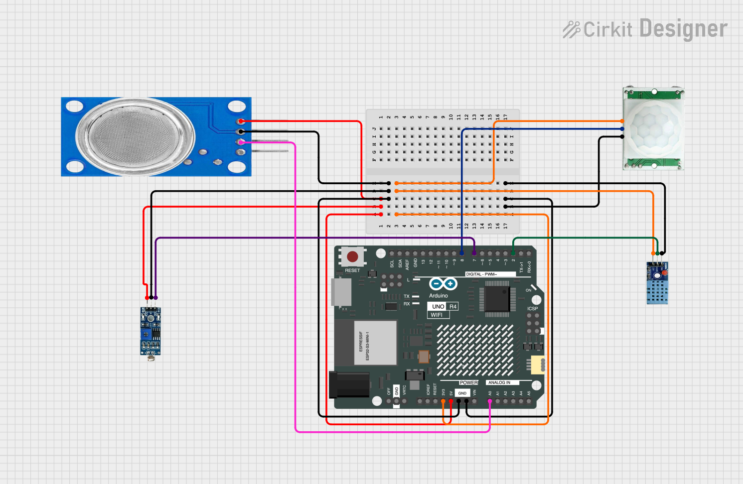

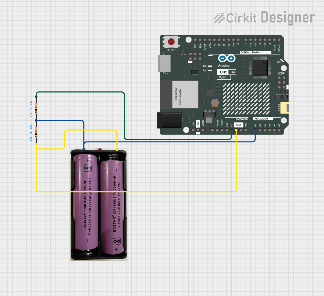
Explore Projects Built with Arduino UNO R4 WiFi
Common Applications and Use Cases
- IoT projects, such as smart sensors and connected devices
- Home automation systems
- Remote data logging and monitoring
- Wireless control of devices
- Educational projects involving internet-connected systems
Technical Specifications
The Arduino UNO R4 WiFi combines the familiar ATmega328P microcontroller with an integrated WiFi module, providing seamless connectivity. Below are the key technical details:
Key Technical Details
| Specification | Value |
|---|---|
| Microcontroller | ATmega328P |
| Operating Voltage | 5V |
| Input Voltage (recommended) | 7-12V |
| Input Voltage (limit) | 6-20V |
| Digital I/O Pins | 14 (6 PWM outputs) |
| Analog Input Pins | 6 |
| DC Current per I/O Pin | 20 mA |
| Flash Memory | 32 KB (0.5 KB used by bootloader) |
| SRAM | 2 KB |
| EEPROM | 1 KB |
| Clock Speed | 16 MHz |
| WiFi Module | Integrated (ESP32-based) |
| Communication Interfaces | UART, SPI, I2C |
| USB Connector | USB-C |
| Dimensions | 68.6 mm x 53.4 mm |
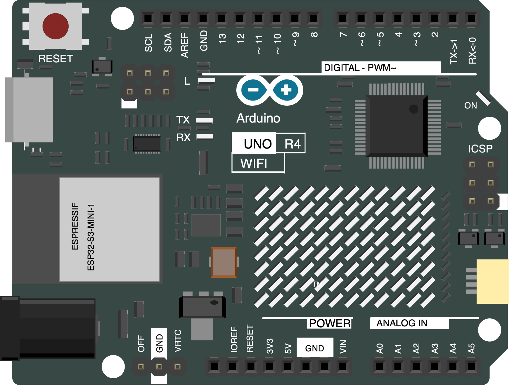
Pin Configuration and Descriptions
The Arduino UNO R4 WiFi features a standard pinout similar to the classic UNO, with additional functionality for WiFi connectivity.
| Pin Number | Pin Name | Description |
|---|---|---|
| 0-1 | RX, TX | UART communication pins |
| 2-13 | Digital I/O | General-purpose digital input/output pins |
| 3, 5, 6, 9, 10, 11 | PWM Pins | Digital pins with PWM output capability |
| A0-A5 | Analog Inputs | Analog input pins (10-bit resolution) |
| GND | Ground | Ground connection |
| 5V | 5V Output | Regulated 5V output |
| 3.3V | 3.3V Output | Regulated 3.3V output |
| VIN | Input Voltage | Input voltage to the board |
| WiFi TX/RX | WiFi Module | Communication pins for the integrated WiFi module |
Usage Instructions
The Arduino UNO R4 WiFi is designed to be user-friendly and compatible with the Arduino IDE. Below are the steps to get started and important considerations for using the board effectively.
How to Use the Component in a Circuit
- Power the Board: Connect the board to your computer using a USB-C cable or supply external power via the VIN pin.
- Install the Arduino IDE: Download and install the latest version of the Arduino IDE from the official Arduino website.
- Select the Board: In the Arduino IDE, go to
Tools > Boardand select "Arduino UNO R4 WiFi." - Connect to WiFi: Use the built-in WiFi library to connect the board to a wireless network.
- Upload Code: Write your program in the Arduino IDE and upload it to the board using the USB-C connection.
Example Code: Connecting to WiFi
Below is an example sketch to connect the Arduino UNO R4 WiFi to a wireless network and print the IP address.
#include <WiFi.h> // Include the WiFi library

const char* ssid = "YourNetworkSSID";     // Replace with your WiFi network name
const char* password = "YourNetworkPass"; // Replace with your WiFi password

void setup() {
  Serial.begin(9600); // Initialize serial communication at 9600 baud
  Serial.println("Connecting to WiFi...");

  // Attempt to connect to the specified WiFi network
  WiFi.begin(ssid, password);

  while (WiFi.status() != WL_CONNECTED) {
    delay(1000); // Wait 1 second before retrying
    Serial.println("Connecting...");
  }

  // Print the IP address once connected
  Serial.println("Connected to WiFi!");
  Serial.print("IP Address: ");
  Serial.println(WiFi.localIP());
}

void loop() {
  // Main loop does nothing in this example
}
Important Considerations and Best Practices
- Ensure the power supply voltage does not exceed the recommended range (7-12V).
- Use proper decoupling capacitors when connecting external components to reduce noise.
- Avoid drawing more than 20 mA from any I/O pin to prevent damage.
- Use the latest version of the Arduino IDE for compatibility with the UNO R4 WiFi.
Troubleshooting and FAQs
Common Issues and Solutions
WiFi Connection Fails:
- Ensure the SSID and password are correct.
- Check if the WiFi network is within range.
- Restart the board and try reconnecting.
Code Upload Fails:
- Verify that the correct board and port are selected in the Arduino IDE.
- Ensure the USB-C cable is properly connected and functional.
Board Not Detected by Computer:
- Install the necessary drivers for the Arduino UNO R4 WiFi.
- Try using a different USB-C cable or port.
WiFi Library Errors:
- Ensure the WiFi library is included in your sketch (
#include <WiFi.h>). - Update the library to the latest version via the Arduino Library Manager.
- Ensure the WiFi library is included in your sketch (
FAQs
Q: Can I use the Arduino UNO R4 WiFi with 3.3V sensors?
A: Yes, the board provides a 3.3V output pin for powering 3.3V sensors and modules.
Q: Is the UNO R4 WiFi compatible with classic UNO shields?
A: Yes, the board maintains the same form factor and pinout as the classic Arduino UNO, ensuring compatibility with most shields.
Q: How do I reset the WiFi module?
A: Use the WiFi.disconnect() function in your sketch to reset the WiFi connection programmatically.
Q: Can I use the board for battery-powered projects?
A: Yes, you can power the board using a battery connected to the VIN pin, but ensure the voltage is within the recommended range.
By following this documentation, you can effectively utilize the Arduino UNO R4 WiFi for a wide range of projects, from simple prototypes to advanced IoT systems.