How to Use Adafruit RFM69HCW Transceiver Radio: Examples, Pinouts, and Specs
Introduction
The Adafruit RFM69HCW Transceiver Radio is a powerful and flexible radio communication module designed for wireless data transmission. Operating in the 915MHz ISM (Industrial, Scientific, and Medical) band, it is capable of both Frequency Shift Keying (FSK) and On-Off Keying (OOK) modulation. This transceiver is ideal for applications such as remote sensing, home automation, and hobbyist projects, offering a significant range of several hundred meters under optimal conditions.
Explore Projects Built with Adafruit RFM69HCW Transceiver Radio


Explore Projects Built with Adafruit RFM69HCW Transceiver Radio
Technical Specifications
Key Technical Details
- Frequency Range: 915 MHz ISM Band
- Modulation Techniques: FSK and OOK
- Supply Voltage: 3.3V to 5V DC
- Output Power: +13 to +20 dBm up to 100 mW Power Output Capability
- Sensitivity: Down to -120 dBm at 1.2 kbps
- Data Rate: 1.2 to 300 kbps
- Operating Temperature: -40°C to +85°C
- Range: Up to several hundred meters (line-of-sight)
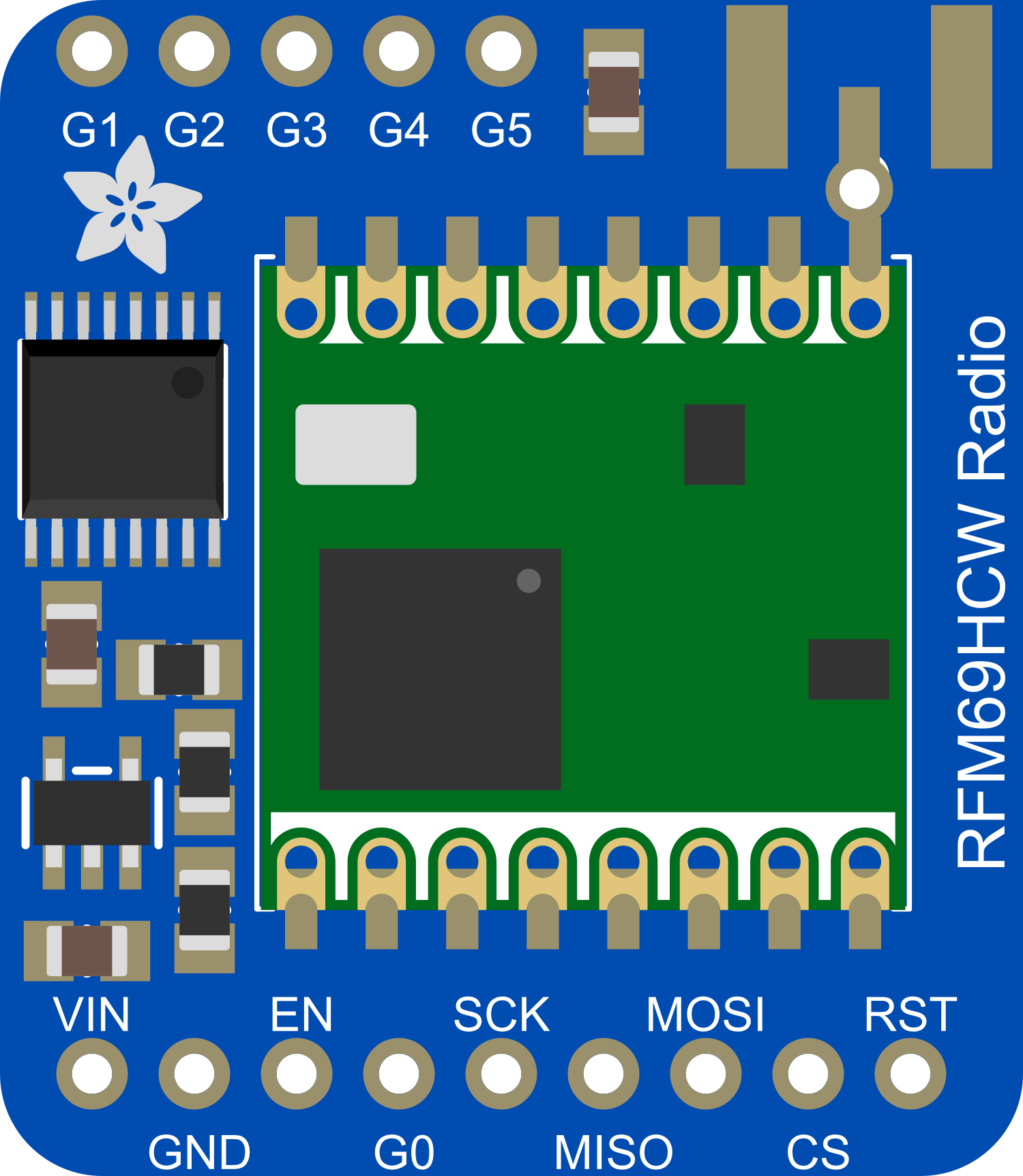
Pin Configuration and Descriptions
| Pin Number | Name | Description |
|---|---|---|
| 1 | GND | Ground connection |
| 2 | VCC | Power supply (3.3V to 5V DC) |
| 3 | DIO0 | Digital I/O for interrupt and packet handling |
| 4 | DIO1 | Digital I/O for interrupt and packet handling |
| 5 | DIO2 | Digital I/O for interrupt and packet handling |
| 6 | DIO3 | Digital I/O for interrupt and packet handling |
| 7 | DIO4 | Digital I/O for interrupt and packet handling |
| 8 | DIO5 | Digital I/O for interrupt and packet handling |
| 9 | SCK | Serial Clock for SPI interface |
| 10 | MISO | Master In Slave Out for SPI interface |
| 11 | MOSI | Master Out Slave In for SPI interface |
| 12 | NSS | Chip Select for SPI interface |
| 13 | RESET | Reset pin |
| 14 | GND | Ground connection |
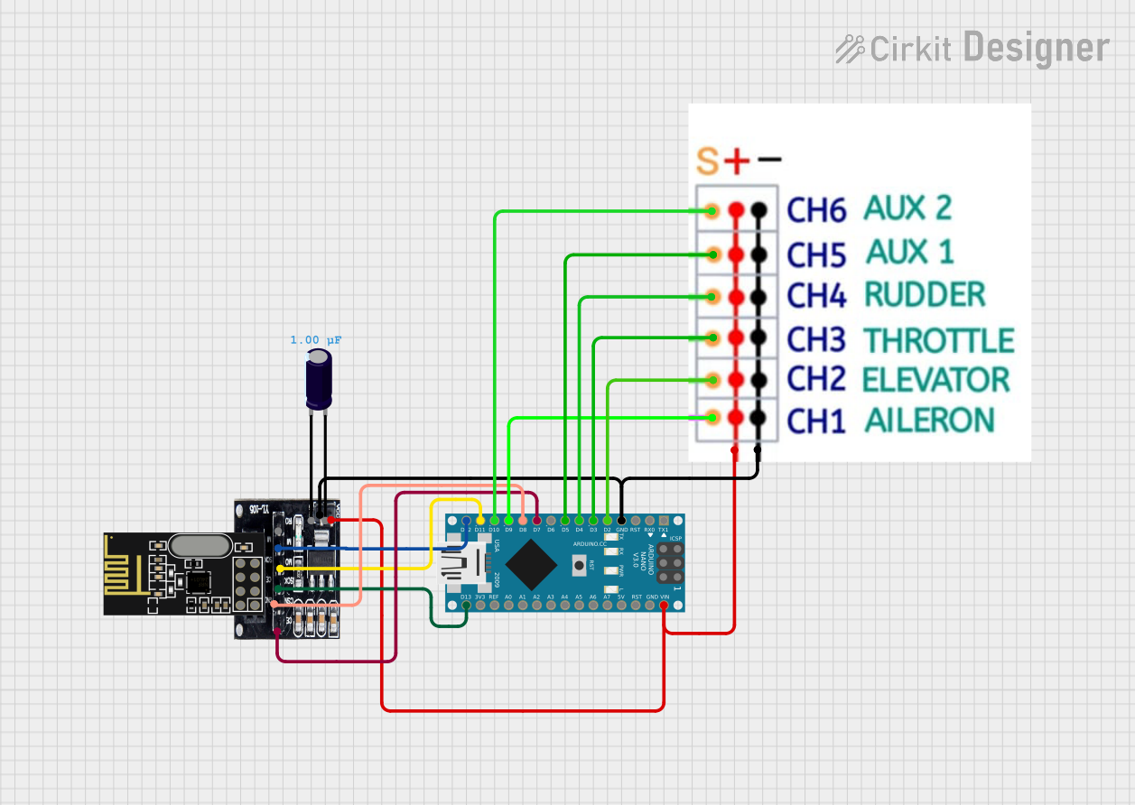
Usage Instructions
Integration with a Circuit
To use the Adafruit RFM69HCW with an Arduino UNO, follow these steps:
- Connect the RFM69HCW's VCC pin to the 3.3V output on the Arduino.
- Connect the GND pins to the Arduino's ground.
- Connect the SCK, MISO, MOSI, and NSS pins to the corresponding SPI pins on the Arduino.
- Connect DIO0 to an interrupt-capable pin on the Arduino for packet handling.
- Optionally, connect other DIO pins if required by your application.
Best Practices
- Always use a logic level converter when connecting the RFM69HCW to a 5V logic device to prevent damage.
- Ensure that the antenna is properly connected and suited for the 915MHz frequency band.
- Keep the RFM69HCW away from metal objects and electronic interference for optimal range.
- Use capacitors for power supply filtering if you encounter noise issues.
Example Arduino Code
#include <SPI.h>
#include <RFM69.h>

#define RFM69_CS      10  // Define the chip select pin
#define RFM69_IRQ     2   // Define the interrupt pin
#define RFM69_IRQN    digitalPinToInterrupt(RFM69_IRQ)
#define FREQUENCY     RF69_915MHZ

RFM69 radio(RFM69_CS, RFM69_IRQ, true);

void setup() {
  Serial.begin(9600);
  while (!Serial); // Wait until the serial console is open
  if (!radio.initialize(FREQUENCY, 1, 0x01)) { // Initialize the RFM69HCW
    Serial.println("RFM69 radio initialization failed");
    while (1);
  }
  radio.setHighPower(); // Only for RFM69HCW & HW!
  radio.encrypt("sampleEncryptKey"); // Optional encryption
}

void loop() {
  // Send a message every 5 seconds
  if (radio.sendWithRetry(2, "Hello World", 11)) { // Target node ID, message, length
    Serial.println("Message sent successfully!");
  }
  delay(5000);
}
Troubleshooting and FAQs
Common Issues
- No Communication: Ensure that the wiring is correct and the power supply is within the specified range.
- Short Range: Check the antenna and ensure there are no obstructions or interference sources nearby.
- Intermittent Operation: Verify that the power supply is stable and filtered.
Solutions and Tips
- Power Issues: Use a dedicated 3.3V regulator if the Arduino's 3.3V supply is insufficient.
- Antenna Tuning: Use an antenna specifically designed for the 915MHz band for better performance.
- SPI Issues: Double-check the SPI connections and ensure that there are no conflicting devices on the SPI bus.
FAQs
Q: Can I use the RFM69HCW with a 5V Arduino? A: Yes, but you must use a logic level converter for the data lines.
Q: What is the maximum data rate? A: The RFM69HCW supports data rates from 1.2 to 300 kbps.
Q: Can I use multiple RFM69HCW modules in a network? A: Yes, the RFM69HCW can be used in a mesh network with unique node addresses.
For further assistance, consult the Adafruit RFM69HCW datasheet and the online community forums dedicated to RFM69HCW projects.