Cirkit Designer Logo
Cirkit Designer
Your all-in-one circuit design IDE
Home / 
Component Documentation

How to Use USB Type A Female Breakout Board : Examples, Pinouts, and Specs

Image of USB Type A Female Breakout Board
Cirkit Designer LogoDesign with USB Type A Female Breakout Board in Cirkit Designer

Introduction

The USB Type A Female Breakout Board is an essential component for hobbyists and professionals who need to integrate USB connectivity into their projects. This breakout board simplifies the process of connecting a USB device to a microcontroller, such as an Arduino UNO, or any other circuit. Common applications include USB data logging, USB power supply for small devices, and interfacing with USB peripherals like keyboards, mice, and storage devices.

Explore Projects Built with USB Type A Female Breakout Board

Use Cirkit Designer to design, explore, and prototype these projects online. Some projects support real-time simulation. Click "Open Project" to start designing instantly!
ESP32 CAM Wi-Fi Enabled Camera Module with USB Power
Image of abc: A project utilizing USB Type A Female Breakout Board  in a practical application
This circuit consists of an ESP32 CAM module powered by a Micro USB breakout board. The USB breakout board supplies 5V and ground to the ESP32 CAM, enabling it to function and perform tasks such as image capture and processing.
Cirkit Designer LogoOpen Project in Cirkit Designer
Raspberry Pi 3B Powered 15.6-inch Touchscreen Display with USB Type-C Power Delivery
Image of Pi Touch Screen Kiosk: A project utilizing USB Type A Female Breakout Board  in a practical application
This circuit powers a 15.6-inch capacitive touch display and a Raspberry Pi 3B using a USB Type C power delivery breakout and two buck converters. The Raspberry Pi connects to the display via HDMI and USB for touch functionality, while the power delivery breakout provides regulated power to both the display and the Raspberry Pi through the buck converters.
Cirkit Designer LogoOpen Project in Cirkit Designer
USB Type-C Powered LED Circuit with Resistor
Image of Scheme1: A project utilizing USB Type A Female Breakout Board  in a practical application
This circuit consists of a USB Type-C port providing power to a red LED through a 1000 Ohm resistor. The resistor limits the current flowing through the LED, which lights up when the circuit is powered.
Cirkit Designer LogoOpen Project in Cirkit Designer
ESP32-CAM and IR Sensor Interface with USB UART Communication
Image of esp32cam parking: A project utilizing USB Type A Female Breakout Board  in a practical application
This circuit features an ESP32 CAM module interfaced with an IR sensor and a SparkFun USB UART Breakout board. The ESP32 CAM provides power to the IR sensor and receives its output signal, likely for processing or triggering camera actions based on IR detection. The USB UART Breakout board is connected to the ESP32 CAM for serial communication, enabling programming, debugging, or data exchange with a computer.
Cirkit Designer LogoOpen Project in Cirkit Designer

Explore Projects Built with USB Type A Female Breakout Board

Use Cirkit Designer to design, explore, and prototype these projects online. Some projects support real-time simulation. Click "Open Project" to start designing instantly!
Image of abc: A project utilizing USB Type A Female Breakout Board  in a practical application
ESP32 CAM Wi-Fi Enabled Camera Module with USB Power
This circuit consists of an ESP32 CAM module powered by a Micro USB breakout board. The USB breakout board supplies 5V and ground to the ESP32 CAM, enabling it to function and perform tasks such as image capture and processing.
Cirkit Designer LogoOpen Project in Cirkit Designer
Image of Pi Touch Screen Kiosk: A project utilizing USB Type A Female Breakout Board  in a practical application
Raspberry Pi 3B Powered 15.6-inch Touchscreen Display with USB Type-C Power Delivery
This circuit powers a 15.6-inch capacitive touch display and a Raspberry Pi 3B using a USB Type C power delivery breakout and two buck converters. The Raspberry Pi connects to the display via HDMI and USB for touch functionality, while the power delivery breakout provides regulated power to both the display and the Raspberry Pi through the buck converters.
Cirkit Designer LogoOpen Project in Cirkit Designer
Image of Scheme1: A project utilizing USB Type A Female Breakout Board  in a practical application
USB Type-C Powered LED Circuit with Resistor
This circuit consists of a USB Type-C port providing power to a red LED through a 1000 Ohm resistor. The resistor limits the current flowing through the LED, which lights up when the circuit is powered.
Cirkit Designer LogoOpen Project in Cirkit Designer
Image of esp32cam parking: A project utilizing USB Type A Female Breakout Board  in a practical application
ESP32-CAM and IR Sensor Interface with USB UART Communication
This circuit features an ESP32 CAM module interfaced with an IR sensor and a SparkFun USB UART Breakout board. The ESP32 CAM provides power to the IR sensor and receives its output signal, likely for processing or triggering camera actions based on IR detection. The USB UART Breakout board is connected to the ESP32 CAM for serial communication, enabling programming, debugging, or data exchange with a computer.
Cirkit Designer LogoOpen Project in Cirkit Designer

Technical Specifications

Key Technical Details

  • Voltage Rating: 5V (typical USB power line)
  • Current Rating: Up to 1.5A (depending on PCB trace thickness)
  • Signal Integrity: Maintains USB 2.0 data rates up to 480 Mbps

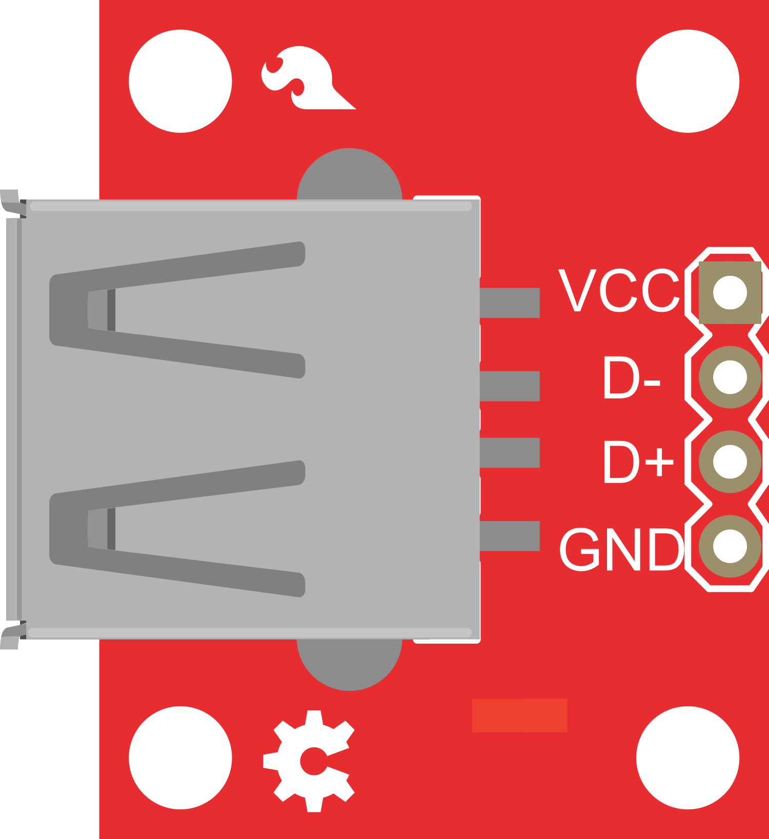
Pin Configuration and Descriptions

Pin Number Description Notes
1 VBUS (Power) 5V from USB host
2 D- (Data minus) USB data line
3 D+ (Data plus) USB data line
4 GND (Ground) Ground reference
Shell Shield Connected to the USB connector's metal casing

Usage Instructions

Integrating with a Circuit

  1. Power Connections: Connect the VBUS and GND pins to your power supply circuit. Ensure that the power supply can handle the current requirements of the USB device.
  2. Data Connections: Connect the D+ and D- pins to the data lines on your microcontroller or USB interface chip.
  3. Shield Connection: The shield pin should be connected to the ground plane of your PCB to ensure proper electromagnetic interference (EMI) shielding.

Important Considerations and Best Practices

  • Power Decoupling: Place a 0.1 µF ceramic capacitor close to the VBUS and GND pins to filter out voltage spikes.
  • Data Line Termination: Use 90-ohm differential impedance for USB data lines and consider termination resistors if required by your USB transceiver.
  • PCB Layout: Keep the data lines as short as possible and route them away from high-frequency signals to minimize cross-talk.
  • ESD Protection: Implement electrostatic discharge (ESD) protection on the data lines to prevent damage from static discharges.

Example Arduino UNO Connection

// This example demonstrates how to set up a USB Type A Female Breakout Board with an Arduino UNO.

void setup() {
  // Initialize the USB interface.
  Serial.begin(9600);
  // Other setup code specific to your project goes here.
}

void loop() {
  // Your main code would handle USB communication here.
  // This could involve reading from or writing to the USB lines.
  // Note: Direct USB communication requires additional hardware and firmware.
}

Troubleshooting and FAQs

Common Issues

  • Device Not Recognized: Ensure that all connections are secure and that the USB device is powered correctly.
  • Data Transfer Errors: Check the integrity of the data lines and ensure they are not too long or placed near noisy components.

Solutions and Tips

  • Secure Connections: Use a multimeter to verify continuity for each connection.
  • Signal Quality: If experiencing data errors, consider using a USB protocol analyzer to diagnose signal issues.

FAQs

Q: Can I power my Arduino UNO through this breakout board? A: Yes, you can supply power to the Arduino UNO by connecting the VBUS pin to the VIN pin on the Arduino and GND to GND.

Q: Do I need additional components to use this breakout board with an Arduino? A: For basic power applications, no additional components are needed. For USB data communication, you will need a USB host shield or similar hardware.

Q: How can I protect my circuit from USB power surges? A: Use a fuse or a polyfuse on the VBUS line and consider adding a transient voltage suppressor (TVS) diode for additional protection.

Remember, this documentation provides a general overview and some specific use cases. Your application may require additional considerations based on the complexity and requirements of your project.