Cirkit Designer
Your all-in-one circuit design IDE
Home /
Component Documentation
How to Use plc+HMI: Examples, Pinouts, and Specs
Introduction
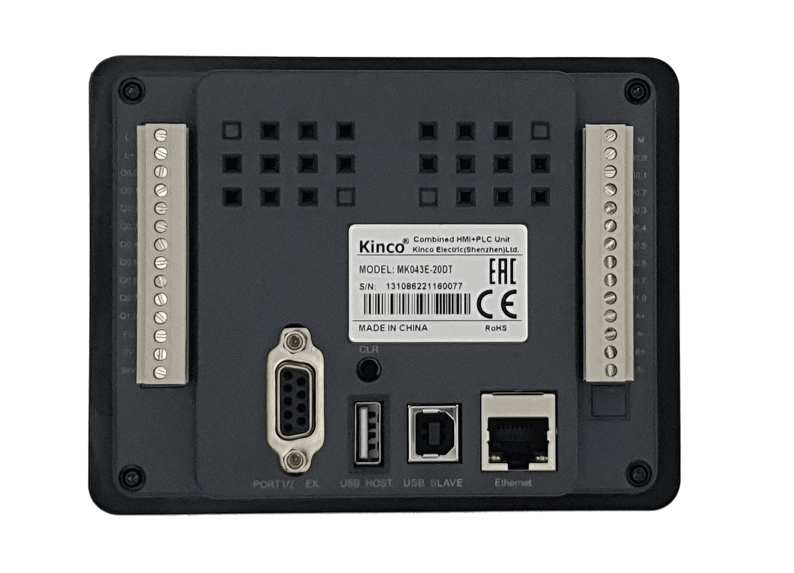
The Kinco MK043E-20DT is a compact and versatile Programmable Logic Controller (PLC) integrated with a Human-Machine Interface (HMI). This all-in-one device combines the control capabilities of a PLC with the user-friendly graphical interface of an HMI, making it ideal for industrial automation applications. The MK043E-20DT is designed to streamline system integration, reduce wiring complexity, and enhance operational efficiency.
Explore Projects Built with plc+HMI
PLC-Controlled Power Window System with Infrared Sensing and Relay Module

This circuit is designed to control a motorized window system using a PLC (Programmable Logic Controller) and an array of sensors and switches. It includes power supplies for 12V and 24V DC, an MCB (Miniature Circuit Breaker) for protection, and a relay module interfaced with an Arduino for additional control logic. The PLC manages inputs from pushbuttons, a 3-position switch, infrared proximity sensors, and an emergency stop, and it controls outputs such as the motor speed controller, lamps, and solenoid valves.
Arduino UNO-Based Conveyor Control System with Multiple I2C LCD Displays and Emergency Stop
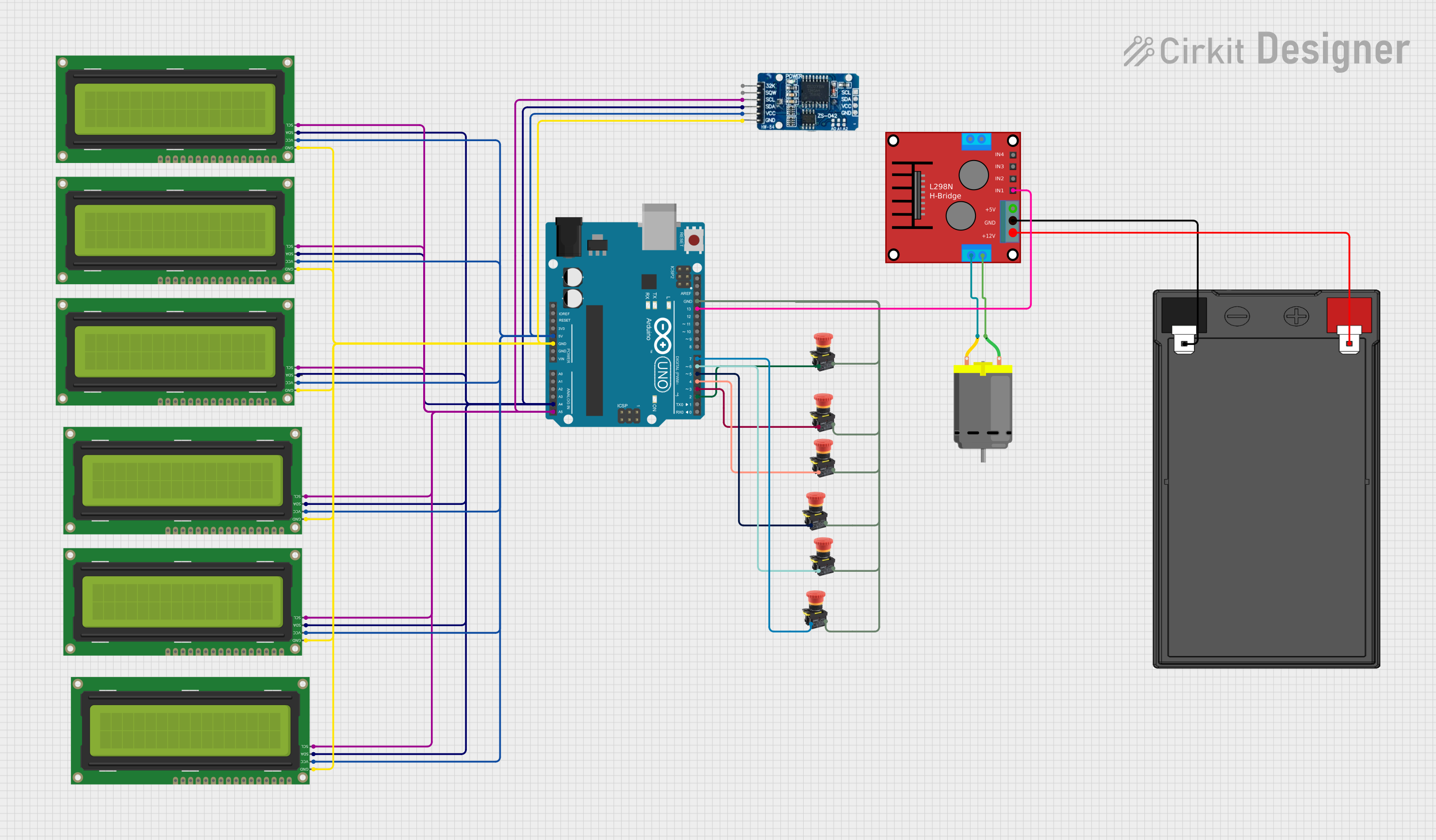
This circuit is a monitoring and control system for a conveyor belt, utilizing an Arduino UNO to interface with six 16x2 I2C LCDs and an RTC module to display real-time data and downtime information. The system includes multiple emergency stop buttons to halt the conveyor, and a motor driver to control a DC motor for the conveyor's movement.
Automated Hydroponic System with Raspberry Pi and Arduino Control

This is a complex control system designed for automation tasks, featuring motion control with stepper motors, environmental sensing, and time-based operations. It includes power management, actuator control via relays, and a user interface provided by a Raspberry Pi connected to a touchscreen display.
PLC and Arduino Controlled Multi-Stepper Motor System
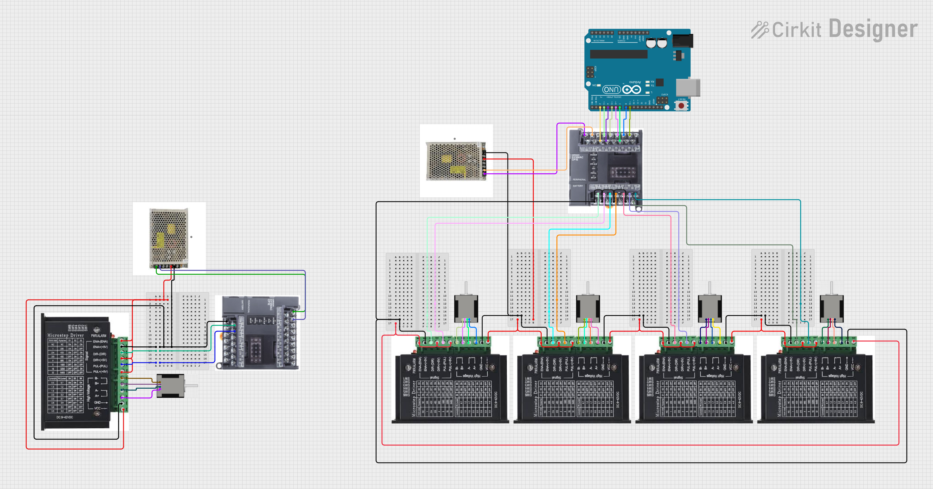
This circuit controls multiple NEMA 17 stepper motors using stepper drivers, a PLC, and an Arduino UNO. The PLC and Arduino coordinate to send control signals to the stepper drivers, which in turn drive the stepper motors. A 24V DC power supply provides the necessary power to the stepper drivers and PLC.
Explore Projects Built with plc+HMI
PLC-Controlled Power Window System with Infrared Sensing and Relay Module
This circuit is designed to control a motorized window system using a PLC (Programmable Logic Controller) and an array of sensors and switches. It includes power supplies for 12V and 24V DC, an MCB (Miniature Circuit Breaker) for protection, and a relay module interfaced with an Arduino for additional control logic. The PLC manages inputs from pushbuttons, a 3-position switch, infrared proximity sensors, and an emergency stop, and it controls outputs such as the motor speed controller, lamps, and solenoid valves.
Arduino UNO-Based Conveyor Control System with Multiple I2C LCD Displays and Emergency Stop
This circuit is a monitoring and control system for a conveyor belt, utilizing an Arduino UNO to interface with six 16x2 I2C LCDs and an RTC module to display real-time data and downtime information. The system includes multiple emergency stop buttons to halt the conveyor, and a motor driver to control a DC motor for the conveyor's movement.
Automated Hydroponic System with Raspberry Pi and Arduino Control
This is a complex control system designed for automation tasks, featuring motion control with stepper motors, environmental sensing, and time-based operations. It includes power management, actuator control via relays, and a user interface provided by a Raspberry Pi connected to a touchscreen display.
PLC and Arduino Controlled Multi-Stepper Motor System
This circuit controls multiple NEMA 17 stepper motors using stepper drivers, a PLC, and an Arduino UNO. The PLC and Arduino coordinate to send control signals to the stepper drivers, which in turn drive the stepper motors. A 24V DC power supply provides the necessary power to the stepper drivers and PLC.
Common Applications and Use Cases
- Industrial automation and process control
- Machine control and monitoring
- Building automation systems
- Packaging and assembly lines
- Data acquisition and visualization
Technical Specifications
Key Technical Details
| Parameter | Specification |
|---|---|
| Manufacturer | Kinco |
| Model | MK043E-20DT |
| Display Size | 4.3 inches (TFT LCD) |
| Resolution | 480 x 272 pixels |
| PLC Type | Digital I/O with relay outputs |
| Input Voltage | 24V DC |
| Digital Inputs | 12 channels |
| Digital Outputs | 8 channels (relay type) |
| Communication Ports | RS232, RS485, Ethernet |
| Programming Software | Kinco DTools |
| Operating Temperature | -10°C to 50°C |
| Storage Temperature | -20°C to 60°C |
| Dimensions | 128mm x 102mm x 38mm |
Pin Configuration and Descriptions
Digital Input Pins
| Pin Number | Description | Voltage Range |
|---|---|---|
| DI0-DI11 | Digital Input Channels | 0-24V DC |
Digital Output Pins
| Pin Number | Description | Output Type |
|---|---|---|
| DO0-DO7 | Digital Output Channels | Relay (max 2A @ 30V DC or 250V AC) |
Communication Ports
| Port | Description | Protocols Supported |
|---|---|---|
| RS232 | Serial Communication | Modbus RTU |
| RS485 | Serial Communication | Modbus RTU |
| Ethernet | Network Communication | Modbus TCP/IP |
Usage Instructions
How to Use the Component in a Circuit
- Power Supply: Connect a regulated 24V DC power supply to the power input terminals of the MK043E-20DT.
- Digital Inputs: Wire sensors, switches, or other input devices to the digital input pins (DI0-DI11). Ensure the input voltage does not exceed 24V DC.
- Digital Outputs: Connect actuators, relays, or other output devices to the digital output pins (DO0-DO7). Verify that the load current does not exceed 2A per channel.
- Communication: Use the RS232, RS485, or Ethernet ports to interface with other devices or systems. Configure the communication settings (e.g., baud rate, parity) in the Kinco DTools software.
- Programming: Develop and upload your control logic using Kinco DTools. The software supports ladder logic programming and HMI screen design.
Important Considerations and Best Practices
- Power Supply: Use a stable and noise-free 24V DC power source to avoid malfunctions.
- Isolation: For noisy environments, consider using optocouplers or isolation modules for the digital inputs and outputs.
- Grounding: Properly ground the device to prevent electrical interference.
- HMI Design: Keep the HMI interface intuitive and user-friendly for operators.
- Firmware Updates: Regularly check for firmware updates from Kinco to ensure optimal performance.
Example Code for Arduino UNO Integration
The MK043E-20DT can communicate with an Arduino UNO via Modbus RTU over RS485. Below is an example Arduino sketch for reading a digital input from the PLC.
#include <ModbusMaster.h> // Include the ModbusMaster library

// Instantiate ModbusMaster object
ModbusMaster node;

void setup() {
  Serial.begin(9600); // Initialize serial communication
  node.begin(1, Serial); // Set Modbus slave ID to 1 and use Serial for communication
}

void loop() {
  uint8_t result;
  uint16_t data;

  // Read digital input status from PLC (address 0x0000)
  result = node.readDiscreteInputs(0x0000, 1);

  if (result == node.ku8MBSuccess) {
    data = node.getResponseBuffer(0); // Get the input status
    Serial.print("Digital Input Status: ");
    Serial.println(data); // Print the status to the serial monitor
  } else {
    Serial.println("Failed to read from PLC"); // Print error message
  }

  delay(1000); // Wait for 1 second before the next read
}
Troubleshooting and FAQs
Common Issues Users Might Face
No Power to the Device:
- Cause: Incorrect or unstable power supply.
- Solution: Verify the power supply voltage is 24V DC and properly connected.
Communication Failure:
- Cause: Incorrect communication settings or wiring.
- Solution: Double-check the baud rate, parity, and wiring connections. Ensure the correct communication protocol (e.g., Modbus RTU) is selected.
Digital Inputs Not Responding:
- Cause: Faulty wiring or incompatible input voltage.
- Solution: Verify the input voltage is within the 0-24V DC range and check the wiring.
Digital Outputs Not Activating:
- Cause: Overloaded output channel or incorrect wiring.
- Solution: Ensure the load current does not exceed 2A per channel and verify the wiring.
Solutions and Tips for Troubleshooting
- Use a multimeter to check voltage levels at the input and output terminals.
- Test communication ports with diagnostic tools or software to ensure proper functionality.
- Refer to the Kinco MK043E-20DT user manual for detailed error codes and troubleshooting steps.
- Contact Kinco technical support for assistance with unresolved issues.