
How to Use VL53L1X: Examples, Pinouts, and Specs
 Design with VL53L1X in Cirkit Designer
Introduction
The VL53L1X is a time-of-flight (ToF) distance sensor developed by Adafruit. It uses laser technology to measure distances with high accuracy and reliability. This sensor can measure distances ranging from 30 mm to 4 meters, making it ideal for applications requiring precise distance measurement. The VL53L1X is compact, energy-efficient, and capable of operating in various lighting conditions, including complete darkness.
Explore Projects Built with VL53L1X
 Open Project in Cirkit Designer
 Open Project in Cirkit Designer
 Open Project in Cirkit Designer
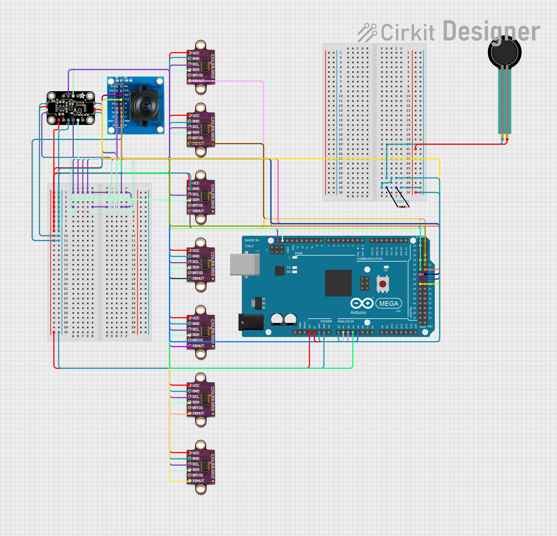 Open Project in Cirkit Designer
Explore Projects Built with VL53L1X
Open Project in Cirkit DesignerOpen Project in Cirkit DesignerOpen Project in Cirkit DesignerOpen Project in Cirkit DesignerCommon Applications and Use Cases
- Robotics for obstacle detection and navigation
- Drones for altitude measurement and collision avoidance
- Industrial automation for object detection
- Smart home devices for presence detection
- Consumer electronics for gesture recognition
Technical Specifications
The VL53L1X sensor is designed to provide accurate distance measurements with minimal power consumption. Below are its key technical details:
| Parameter | Value |
|---|---|
| Operating Voltage | 2.6V to 3.5V |
| Communication Interface | I²C |
| Measurement Range | 30 mm to 4 meters |
| Accuracy | ±1 mm (typical) |
| Field of View (FoV) | Programmable, up to 27° |
| Operating Temperature Range | -20°C to +85°C |
| Power Consumption | 20 mW (typical) |
| Dimensions | 4.4 mm x 2.4 mm x 1.0 mm |
Pin Configuration and Descriptions
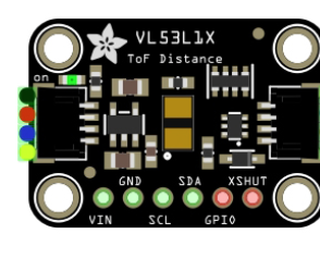
The VL53L1X sensor module typically comes with the following pins:
| Pin Name | Description |
|---|---|
| VIN | Power supply input (2.6V to 5V). Connect to the 3.3V or 5V pin of your microcontroller. |
| GND | Ground connection. Connect to the ground of your circuit. |
| SDA | I²C data line. Connect to the SDA pin of your microcontroller. |
| SCL | I²C clock line. Connect to the SCL pin of your microcontroller. |
| XSHUT | Shutdown pin. Pull low to disable the sensor; leave high or floating to enable. |
| GPIO1 | Interrupt pin. Can be used for custom interrupt configurations. |
Usage Instructions
How to Use the VL53L1X in a Circuit
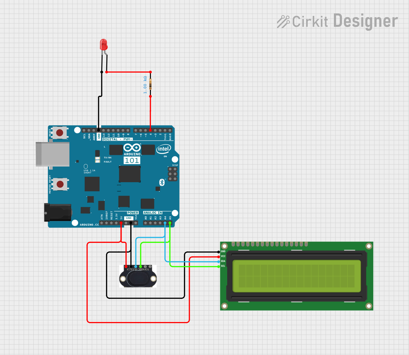
- Power the Sensor: Connect the VIN pin to a 3.3V or 5V power source and the GND pin to ground.
- I²C Communication: Connect the SDA and SCL pins to the corresponding I²C pins on your microcontroller. Use pull-up resistors (typically 4.7 kΩ) if not already included on the breakout board.
- Optional Pins:
- Connect the XSHUT pin to a GPIO pin on your microcontroller if you need to control the sensor's power state programmatically.
- Use the GPIO1 pin for interrupt-based applications if required.
- Install Libraries: If using an Arduino, install the Adafruit VL53L1X library from the Arduino Library Manager.
Important Considerations and Best Practices
- Ensure the sensor is not obstructed and has a clear line of sight to the target for accurate measurements.
- Avoid exposing the sensor to direct sunlight or reflective surfaces, as these can interfere with readings.
- Use proper decoupling capacitors near the VIN pin to stabilize the power supply.
- Keep I²C lines as short as possible to minimize noise and ensure reliable communication.
Example Code for Arduino UNO
Below is an example code to interface the VL53L1X with an Arduino UNO:
#include <Wire.h>
#include <Adafruit_VL53L1X.h>

// Create an instance of the VL53L1X sensor
Adafruit_VL53L1X vl53 = Adafruit_VL53L1X();

void setup() {
  Serial.begin(115200); // Initialize serial communication for debugging
  while (!Serial) delay(10); // Wait for Serial Monitor to open

  Serial.println("Adafruit VL53L1X Test");

  // Initialize the sensor
  if (!vl53.begin()) {
    Serial.println("Failed to find VL53L1X sensor!");
    while (1); // Halt execution if sensor initialization fails
  }

  Serial.println("VL53L1X sensor initialized successfully!");

  // Set the distance mode to long range
  vl53.setDistanceMode(VL53L1X::Long);
  vl53.startRanging(); // Start continuous ranging
}

void loop() {
  // Read the distance in millimeters
  uint16_t distance = vl53.read();

  // Check if the reading is valid
  if (distance != VL53L1X_OUT_OF_RANGE) {
    Serial.print("Distance: ");
    Serial.print(distance);
    Serial.println(" mm");
  } else {
    Serial.println("Out of range");
  }

  delay(100); // Wait 100 ms before the next reading
}
Troubleshooting and FAQs
Common Issues and Solutions
Sensor Not Detected on I²C Bus:
- Ensure the SDA and SCL pins are correctly connected to the microcontroller.
- Verify that pull-up resistors are present on the I²C lines.
- Check the I²C address of the sensor (default is 0x29) and ensure no address conflicts.
Inaccurate Distance Measurements:
- Ensure the sensor has a clear line of sight to the target.
- Avoid reflective or transparent surfaces that can distort readings.
- Verify that the sensor is operating within its specified range (30 mm to 4 meters).
Sensor Fails to Initialize:
- Confirm that the VIN and GND pins are properly connected.
- Check the power supply voltage (2.6V to 5V).
- Ensure the XSHUT pin is not being held low during initialization.
FAQs
Q: Can the VL53L1X measure distances through glass?
A: The sensor may struggle with transparent surfaces like glass, as they can distort the laser signal. For best results, avoid placing glass between the sensor and the target.
Q: What is the maximum I²C clock speed supported by the VL53L1X?
A: The VL53L1X supports I²C clock speeds up to 400 kHz (Fast Mode).
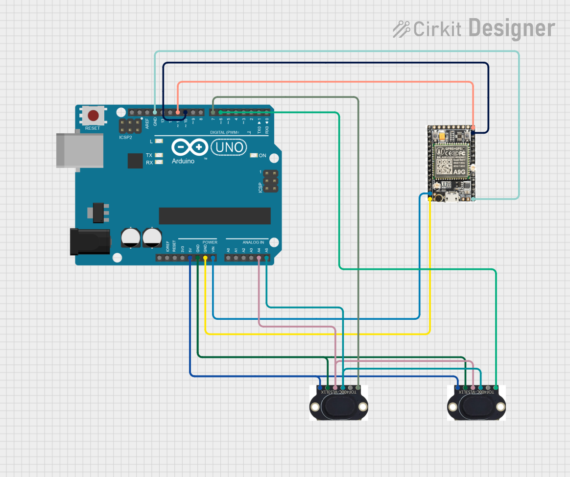
Q: Can I use multiple VL53L1X sensors on the same I²C bus?
A: Yes, but you must change the I²C address of each sensor using the XSHUT pin to avoid address conflicts.
Q: How can I reduce the field of view (FoV)?
A: The VL53L1X allows programmable FoV settings. Refer to the Adafruit library documentation for details on configuring the FoV.
Q: Is the VL53L1X affected by ambient light?
A: The sensor is designed to work in various lighting conditions, including complete darkness. However, extremely bright light sources, such as direct sunlight, may affect performance.