How to Use Step-Down Modul - (6v - 100V) > 5v: Examples, Pinouts, and Specs
Introduction
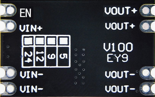
The MakerMind RBS17520 is a high-efficiency step-down module (buck converter) designed to convert a wide range of input voltages (6V to 100V) into a stable 5V output. This module is ideal for powering low-voltage devices such as microcontrollers, sensors, and other 5V electronics from higher voltage sources like batteries, solar panels, or industrial power supplies.
Explore Projects Built with Step-Down Modul - (6v - 100V) > 5v


Explore Projects Built with Step-Down Modul - (6v - 100V) > 5v
Common Applications and Use Cases
- Powering 5V microcontrollers (e.g., Arduino, Raspberry Pi)
- Voltage regulation in battery-powered systems
- Solar-powered projects
- Industrial automation systems
- Automotive electronics
Technical Specifications
Key Technical Details
| Parameter | Value |
|---|---|
| Manufacturer | MakerMind |
| Part ID | RBS17520 |
| Input Voltage Range | 6V to 100V |
| Output Voltage | 5V (fixed) |
| Maximum Output Current | 3A |
| Efficiency | Up to 95% |
| Operating Temperature | -40°C to +85°C |
| Dimensions | 25mm x 20mm x 10mm |
| Weight | 10g |
Pin Configuration and Descriptions
| Pin Name | Pin Type | Description |
|---|---|---|
| VIN+ | Input | Positive input voltage (6V to 100V) |
| VIN- | Input | Negative input voltage (ground) |
| VOUT+ | Output | Positive 5V output voltage |
| VOUT- | Output | Negative output voltage (ground) |
Usage Instructions
How to Use the Component in a Circuit
Connect the Input Voltage:
- Attach the positive terminal of your power source (6V to 100V) to the
VIN+pin. - Connect the negative terminal of your power source to the
VIN-pin.
- Attach the positive terminal of your power source (6V to 100V) to the
Connect the Output Voltage:
- Connect the
VOUT+pin to the positive terminal of your 5V device. - Connect the
VOUT-pin to the ground terminal of your 5V device.
- Connect the
Verify Connections:
- Double-check all connections to ensure proper polarity and avoid short circuits.
Power On:
- Turn on the power source. The module will automatically regulate the input voltage to a stable 5V output.
Important Considerations and Best Practices
- Input Voltage Range: Ensure the input voltage is within the specified range (6V to 100V). Exceeding this range may damage the module.
- Heat Dissipation: For high current loads (above 2A), consider adding a heatsink or active cooling to prevent overheating.
- Polarity Protection: The module does not have built-in reverse polarity protection. Always connect the input and output terminals correctly.
- Load Testing: Before connecting sensitive devices, test the output voltage with a multimeter to confirm it is stable at 5V.
Example: Using with an Arduino UNO
The RBS17520 can be used to power an Arduino UNO from a 12V battery. Below is an example circuit and Arduino code to blink an LED:
Circuit Connections
- Connect the 12V battery's positive terminal to
VIN+and negative terminal toVIN-. - Connect
VOUT+to the Arduino's 5V pin andVOUT-to the Arduino's GND pin. - Connect an LED to pin 13 of the Arduino with a 220-ohm resistor in series.
Arduino Code
// Simple LED Blink Example
// This code blinks an LED connected to pin 13 of the Arduino UNO.

void setup() {
  pinMode(13, OUTPUT); // Set pin 13 as an output
}

void loop() {
  digitalWrite(13, HIGH); // Turn the LED on
  delay(1000);            // Wait for 1 second
  digitalWrite(13, LOW);  // Turn the LED off
  delay(1000);            // Wait for 1 second
}
Troubleshooting and FAQs
Common Issues and Solutions
| Issue | Possible Cause | Solution |
|---|---|---|
| No output voltage | Incorrect wiring or loose connections | Verify all connections and polarity. |
| Output voltage fluctuates | Input voltage is unstable | Use a capacitor (e.g., 100µF) across VIN. |
| Module overheats | Excessive current draw | Add a heatsink or reduce the load. |
| Device not powering on | Insufficient input voltage | Ensure input voltage is at least 6V. |
FAQs
Can I adjust the output voltage?
- No, the RBS17520 provides a fixed 5V output and cannot be adjusted.
What happens if I connect the input voltage in reverse?
- The module does not have reverse polarity protection and may be permanently damaged. Always double-check connections.
Can I use this module with a solar panel?
- Yes, as long as the solar panel's output voltage is within the 6V to 100V range.
What is the maximum power output of the module?
- The maximum power output is 15W (5V x 3A).
By following this documentation, you can effectively integrate the MakerMind RBS17520 step-down module into your projects.