
How to Use MIC4575 (TO220): Examples, Pinouts, and Specs
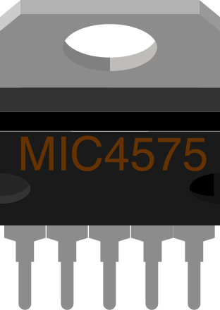
 Design with MIC4575 (TO220) in Cirkit Designer
Introduction
The MIC4575 is a high-performance voltage regulator manufactured by Micrel. It is designed to deliver a stable output voltage with low dropout and high efficiency, making it ideal for power supply applications. The component is housed in a TO-220 package, which provides excellent thermal performance and ease of mounting. The MIC4575 is commonly used in applications such as industrial power supplies, battery-powered devices, and embedded systems requiring efficient voltage regulation.
Explore Projects Built with MIC4575 (TO220)
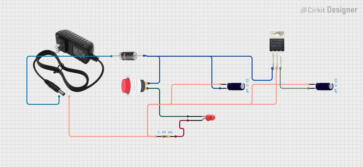 Open Project in Cirkit Designer
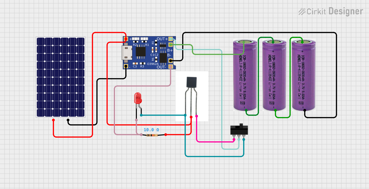 Open Project in Cirkit Designer
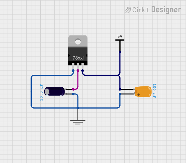 Open Project in Cirkit Designer
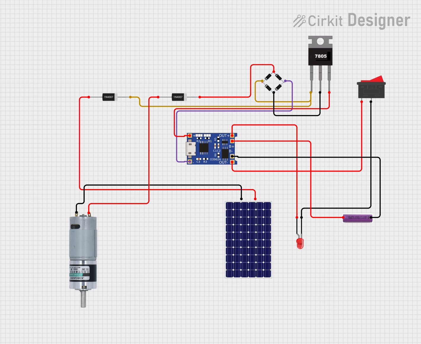 Open Project in Cirkit Designer
Explore Projects Built with MIC4575 (TO220)
Open Project in Cirkit DesignerOpen Project in Cirkit DesignerOpen Project in Cirkit DesignerOpen Project in Cirkit DesignerTechnical Specifications
The MIC4575 is a step-down (buck) voltage regulator with the following key specifications:
| Parameter | Value |
|---|---|
| Input Voltage Range | 4V to 40V |
| Output Voltage Range | Adjustable (1.23V to 37V) |
| Output Current | Up to 1.5A |
| Efficiency | Up to 90% |
| Switching Frequency | 200 kHz |
| Dropout Voltage | 1.4V (typical at full load) |
| Operating Temperature Range | -40°C to +125°C |
| Package Type | TO-220 |
Pin Configuration and Descriptions
The MIC4575 in the TO-220 package has three pins, as described below:
| Pin Number | Pin Name | Description |
|---|---|---|
| 1 | VIN | Input voltage pin. Connect to the unregulated DC input. |
| 2 | GND | Ground pin. Connect to the circuit ground. |
| 3 | VOUT | Regulated output voltage pin. Connect to the load. |
Usage Instructions
How to Use the MIC4575 in a Circuit
- Input Voltage: Ensure the input voltage (VIN) is within the range of 4V to 40V. Use a decoupling capacitor (e.g., 100 µF electrolytic) close to the VIN pin to reduce input noise.
- Output Voltage Adjustment: The MIC4575 allows for an adjustable output voltage. Use an external resistor divider network to set the desired output voltage. The formula for the output voltage is: [ V_{OUT} = V_{REF} \times \left(1 + \frac{R1}{R2}\right) ] where ( V_{REF} ) is 1.23V (reference voltage).
- Inductor Selection: Choose an inductor with a current rating higher than the maximum load current (1.5A) and a suitable inductance value to maintain stable operation.
- Output Capacitor: Use a low ESR capacitor (e.g., 100 µF electrolytic or tantalum) at the output to ensure stability and reduce ripple.
- Diode Selection: Use a Schottky diode (e.g., 1N5819) for the freewheeling diode to improve efficiency and reduce switching losses.
Example Circuit
Below is a basic circuit diagram for using the MIC4575 to regulate a 12V input to a 5V output:
- VIN: 12V DC
- VOUT: 5V DC
- Inductor: 68 µH
- Output Capacitor: 100 µF
- Schottky Diode: 1N5819
Arduino UNO Example Code
The MIC4575 can be used to power an Arduino UNO. Below is an example code snippet to demonstrate how to read the regulated output voltage using the Arduino's ADC:
// Define the analog pin connected to the MIC4575 output
const int voltagePin = A0;

// Reference voltage for ADC (5V for Arduino UNO)
const float referenceVoltage = 5.0;

// ADC resolution (10-bit for Arduino UNO)
const int adcResolution = 1024;

void setup() {
  Serial.begin(9600); // Initialize serial communication
}

void loop() {
  int adcValue = analogRead(voltagePin); // Read ADC value
  // Calculate the output voltage
  float outputVoltage = (adcValue * referenceVoltage) / adcResolution;

  // Print the output voltage to the Serial Monitor
  Serial.print("Output Voltage: ");
  Serial.print(outputVoltage);
  Serial.println(" V");

  delay(1000); // Wait for 1 second before the next reading
}
Important Considerations
- Ensure proper heat dissipation by attaching a heatsink to the TO-220 package if the regulator operates at high currents.
- Use short and thick traces for the input and output connections to minimize resistance and voltage drops.
- Place the input and output capacitors as close as possible to the MIC4575 pins to reduce noise and improve stability.
Troubleshooting and FAQs
Common Issues and Solutions
Output Voltage is Incorrect
- Cause: Incorrect resistor divider values.
- Solution: Verify the resistor values and recalculate using the output voltage formula.
Excessive Heat Generation
- Cause: High input voltage or insufficient heatsinking.
- Solution: Use a heatsink and ensure proper ventilation. Reduce the input voltage if possible.
High Output Ripple
- Cause: Inadequate output capacitor or high ESR.
- Solution: Use a low ESR capacitor with a higher capacitance value.
No Output Voltage
- Cause: Incorrect wiring or damaged component.
- Solution: Check all connections and verify the component is functioning correctly.
FAQs
Can the MIC4575 be used for negative voltage regulation?
- No, the MIC4575 is designed for positive voltage regulation only.
What is the maximum load current the MIC4575 can handle?
- The MIC4575 can handle up to 1.5A of load current.
Can I use the MIC4575 without a heatsink?
- It depends on the load current and input-output voltage difference. For high currents or large voltage drops, a heatsink is recommended.
What type of diode should I use with the MIC4575?
- A Schottky diode, such as the 1N5819, is recommended for its low forward voltage drop and fast switching characteristics.