How to Use TCRT 5000 IR SENSOR schematic: Examples, Pinouts, and Specs
Introduction
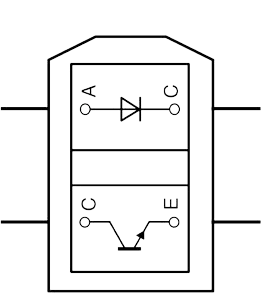
The TCRT 5000 is an infrared (IR) sensor module that consists of an infrared emitter and a phototransistor paired together. It is commonly used for object detection and proximity sensing applications. The sensor works by emitting infrared light and detecting the reflected light using the phototransistor, allowing it to determine the presence or absence of an object within its detection range.
Explore Projects Built with TCRT 5000 IR SENSOR schematic

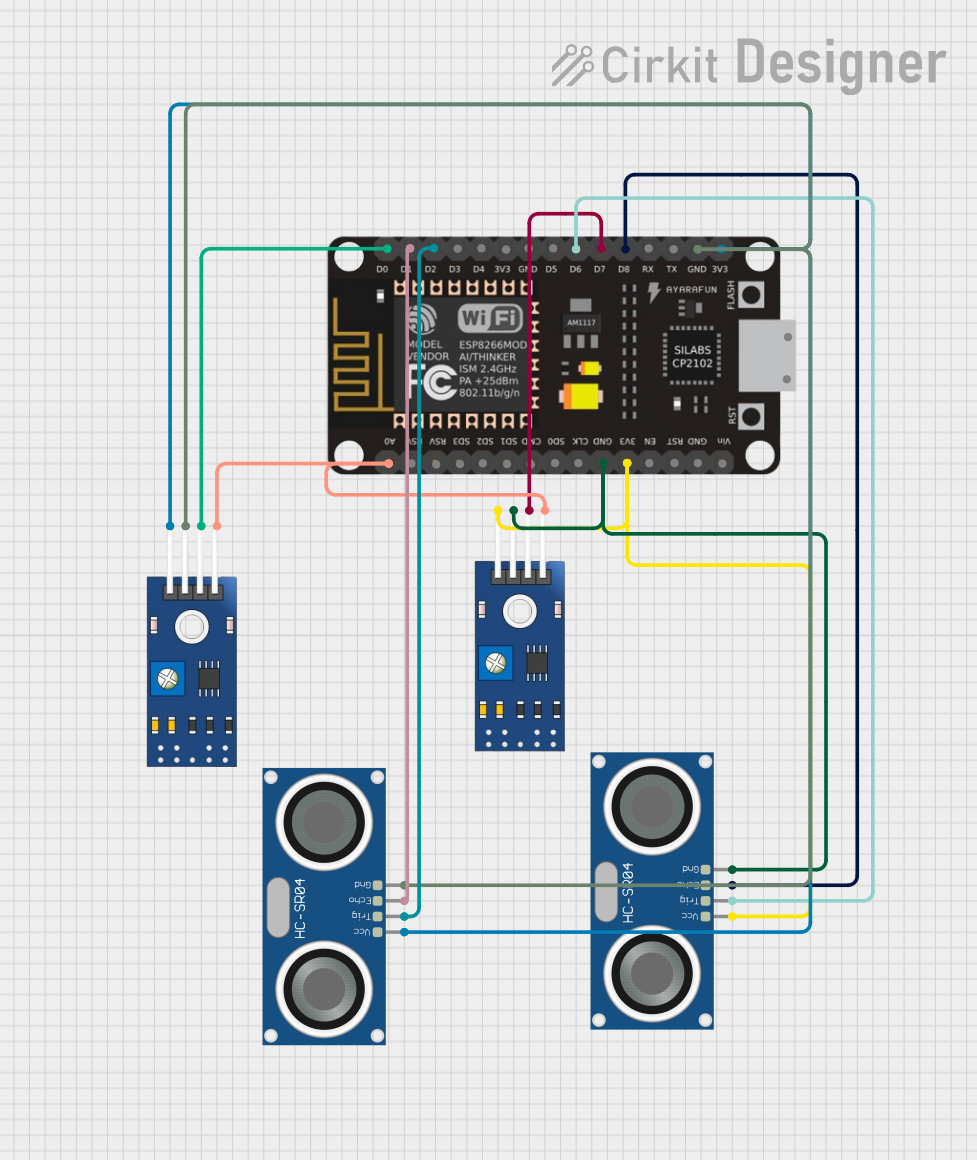
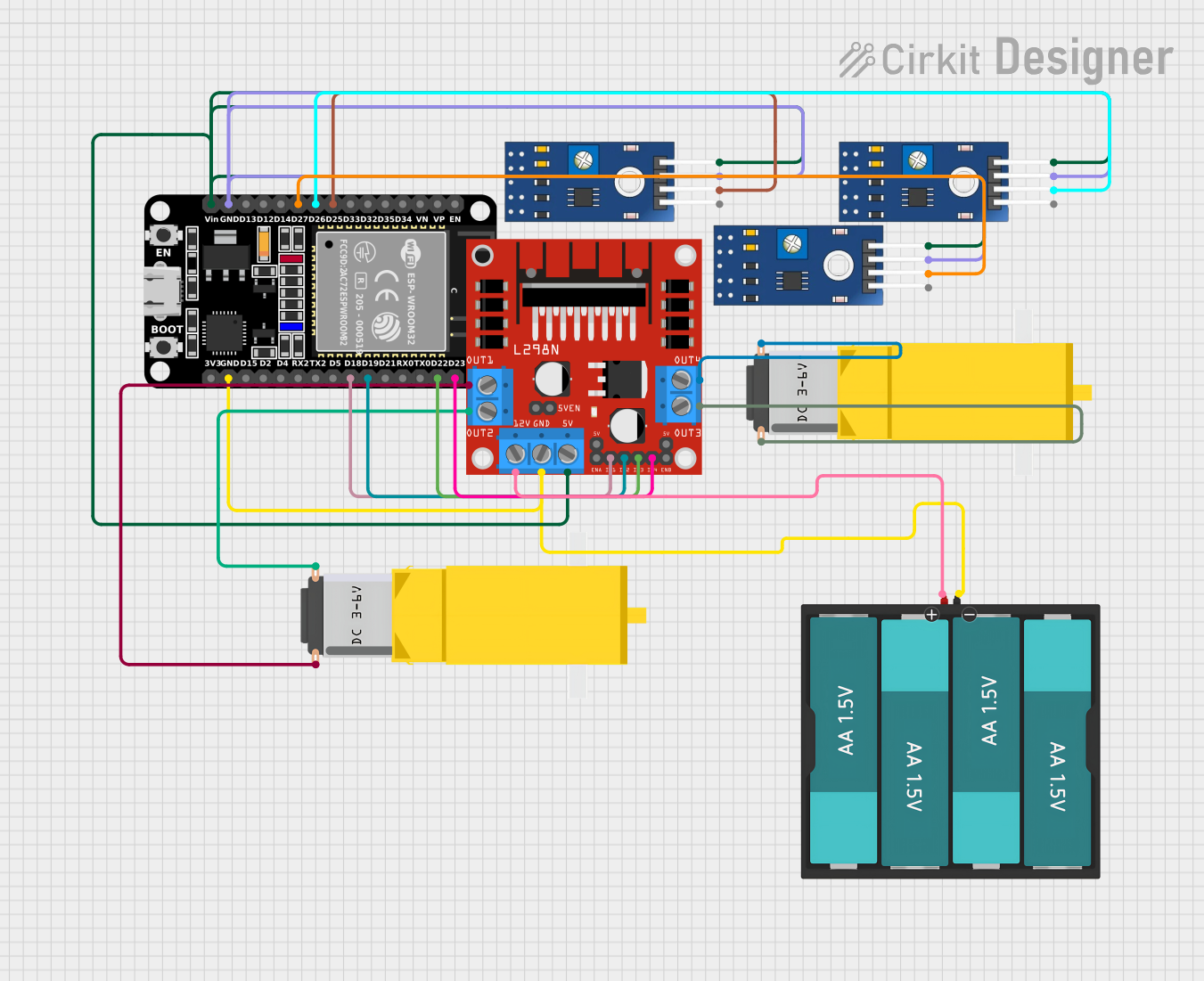
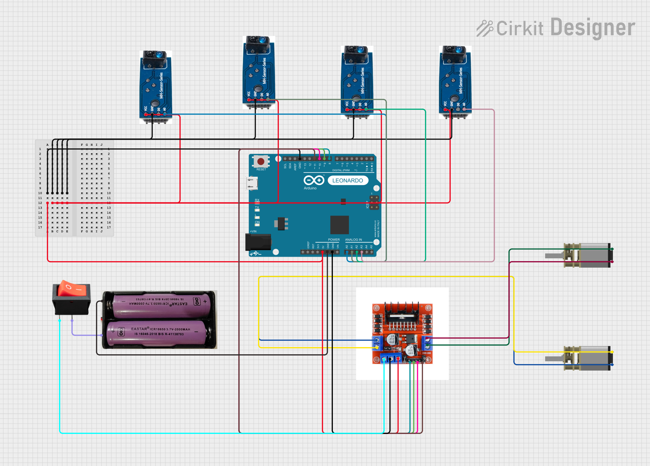
Explore Projects Built with TCRT 5000 IR SENSOR schematic
Common Applications and Use Cases
- Line following robots
- Obstacle avoidance systems
- Position sensors
- Rotary encoders
- Paper/printer jam detectors
Technical Specifications
Key Technical Details
- Operating Voltage: 3.3V to 5V DC
- Average Current Consumption: 20mA
- Peak Emitter Wavelength: 950nm
- Detection Distance: 2mm to 10mm
- Output Type: Analog voltage corresponding to the amount of detected IR light
Pin Configuration and Descriptions
| Pin Number | Name | Description |
|---|---|---|
| 1 | VCC | Power supply (3.3V to 5V DC) |
| 2 | GND | Ground connection |
| 3 | AO | Analog output voltage |
| 4 | DO | Digital output (active low) |
Usage Instructions
How to Use the TCRT 5000 in a Circuit
- Connect the VCC pin to a 3.3V or 5V power supply.
- Connect the GND pin to the ground of the power supply.
- The AO pin provides an analog output voltage that varies with the amount of reflected IR light. Connect this to an analog input on your microcontroller if you need to measure the intensity of the reflection.
- The DO pin provides a digital output that switches low when the intensity of the reflected IR light exceeds a certain threshold. This threshold can be adjusted using the onboard potentiometer. Connect this to a digital input on your microcontroller if you need a simple detection signal.
Important Considerations and Best Practices
- Ensure that the sensor is not exposed to direct sunlight or other strong IR sources, as this can interfere with its operation.
- Adjust the onboard potentiometer carefully to set the detection threshold according to your application needs.
- Keep the sensor clean and free from dust for accurate detection.
- Use a current limiting resistor with the IR LED if you are operating the sensor at the higher end of its voltage range to prevent damage.
Troubleshooting and FAQs
Common Issues
- Sensor not detecting objects: Check the alignment of the emitter and phototransistor, and ensure that the object is within the specified detection range.
- Unstable readings: Ensure that there are no external IR sources interfering with the sensor. Also, check for loose connections and a stable power supply.
- DO pin always high or low: Adjust the onboard potentiometer to calibrate the detection threshold.
Solutions and Tips for Troubleshooting
- If the sensor is not responding, verify that the power supply is within the operating voltage range and that all connections are secure.
- For erratic or unstable sensor readings, consider adding a capacitor between VCC and GND near the sensor to stabilize the power supply.
- Clean the sensor surface gently with a soft, dry cloth if dust or fingerprints are suspected to be affecting the readings.
FAQs
Q: Can the TCRT 5000 detect the color of an object? A: No, the TCRT 5000 is not capable of detecting colors. It only detects the presence of an object based on reflected IR light.
Q: What is the maximum detection range of the TCRT 5000? A: The typical detection range is between 2mm and 10mm, but this can vary depending on the object's surface and the sensor's calibration.
Q: How do I adjust the sensitivity of the sensor? A: Sensitivity can be adjusted by turning the onboard potentiometer. Clockwise rotation generally increases sensitivity, while counterclockwise rotation decreases it.
Example Arduino Code
// TCRT 5000 IR Sensor Example with Arduino UNO
const int analogPin = A0; // Analog output from the sensor
const int digitalPin = 2; // Digital output from the sensor

void setup() {
  Serial.begin(9600);
  pinMode(digitalPin, INPUT);
}

void loop() {
  int analogValue = analogRead(analogPin); // Read the analog value
  bool isObjectDetected = digitalRead(digitalPin) == LOW; // Check digital output

  Serial.print("Analog Value: ");
  Serial.print(analogValue);
  Serial.print(" - Object Detected: ");
  Serial.println(isObjectDetected ? "Yes" : "No");

  delay(100); // Short delay before next reading
}
This example code reads both the analog and digital outputs from the TCRT 5000 sensor and prints the results to the Serial Monitor. The digital output is considered active when it is LOW, indicating that an object has been detected within the sensor's range.