Cirkit Designer Logo
Cirkit Designer
Your all-in-one circuit design IDE
Home / 
Component Documentation

How to Use Adafruit BLM Badge: Examples, Pinouts, and Specs

Image of Adafruit BLM Badge
Cirkit Designer LogoDesign with Adafruit BLM Badge in Cirkit Designer

Introduction

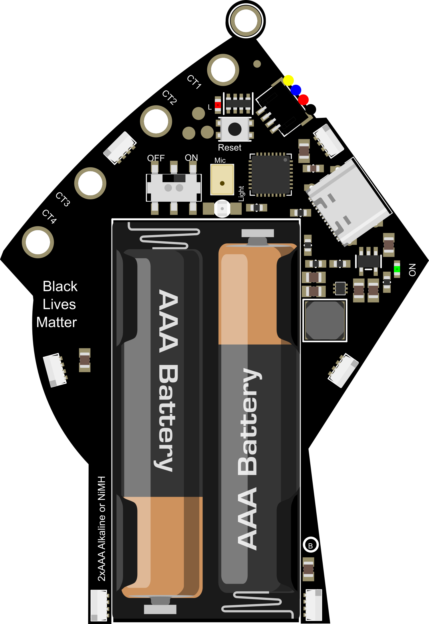
The Adafruit BLM Badge is a versatile and vibrant LED matrix display designed for creating dynamic and colorful patterns, text, and graphics. With its 9x14 array of RGB LEDs, it offers a platform for hobbyists and professionals alike to develop wearable electronics, interactive art installations, and eye-catching displays. The badge is programmable via microcontrollers such as the Arduino UNO, making it accessible for a wide range of users.

Explore Projects Built with Adafruit BLM Badge

Use Cirkit Designer to design, explore, and prototype these projects online. Some projects support real-time simulation. Click "Open Project" to start designing instantly!
Solar-Powered Environmental Data Logger with Adafruit Feather M0 Express
Image of Lake Thoreau Monitoring Station: A project utilizing Adafruit BLM Badge in a practical application
This circuit is designed for environmental data collection and logging, utilizing an Adafruit Feather M0 Express microcontroller as the central processing unit. It interfaces with a BME280 sensor for atmospheric temperature, humidity, and pressure measurements, an SGP30 sensor for monitoring air quality (eCO2 and TVOC), and a STEMMA soil sensor for detecting soil moisture and temperature. The system is powered by a solar panel and a 3.7v LiPo battery, managed by an Adafruit BQ24074 Solar-DC-USB Lipo Charger, and provides easy access to the microcontroller's connections through an Adafruit Terminal Breakout FeatherWing.
Cirkit Designer LogoOpen Project in Cirkit Designer
Arduino UNO Weather Station with BME280 Sensor and I2C LCD Display
Image of WeatherStation: A project utilizing Adafruit BLM Badge in a practical application
This circuit uses an Arduino UNO to read environmental data from a BME/BMP280 sensor and display the information on a 16x2 I2C LCD. Additionally, a green LED is connected through a resistor to indicate the status or provide visual feedback.
Cirkit Designer LogoOpen Project in Cirkit Designer
Arduino Nano Weather Station with OLED Display and BME280 Sensor
Image of bme280 weather station: A project utilizing Adafruit BLM Badge in a practical application
This circuit features an Arduino Nano microcontroller interfaced with a 0.96" OLED display and a BME/BMP280 sensor for environmental monitoring. A pushbutton is connected to the Arduino for user input, and the OLED and sensor share I2C communication lines with the Arduino.
Cirkit Designer LogoOpen Project in Cirkit Designer
Battery-Powered Smart Light with Proximity Sensor and OLED Display using Adafruit QT Py RP2040
Image of lab: A project utilizing Adafruit BLM Badge in a practical application
This circuit is a portable, battery-powered system featuring an Adafruit QT Py RP2040 microcontroller that interfaces with an OLED display, a proximity sensor, an accelerometer, and an RGB LED strip. The system is powered by a lithium-ion battery with a step-up boost converter to provide 5V for the LED strip, and it includes a toggle switch for power control. The microcontroller communicates with the sensors and display via I2C.
Cirkit Designer LogoOpen Project in Cirkit Designer

Explore Projects Built with Adafruit BLM Badge

Use Cirkit Designer to design, explore, and prototype these projects online. Some projects support real-time simulation. Click "Open Project" to start designing instantly!
Image of Lake Thoreau Monitoring Station: A project utilizing Adafruit BLM Badge in a practical application
Solar-Powered Environmental Data Logger with Adafruit Feather M0 Express
This circuit is designed for environmental data collection and logging, utilizing an Adafruit Feather M0 Express microcontroller as the central processing unit. It interfaces with a BME280 sensor for atmospheric temperature, humidity, and pressure measurements, an SGP30 sensor for monitoring air quality (eCO2 and TVOC), and a STEMMA soil sensor for detecting soil moisture and temperature. The system is powered by a solar panel and a 3.7v LiPo battery, managed by an Adafruit BQ24074 Solar-DC-USB Lipo Charger, and provides easy access to the microcontroller's connections through an Adafruit Terminal Breakout FeatherWing.
Cirkit Designer LogoOpen Project in Cirkit Designer
Image of WeatherStation: A project utilizing Adafruit BLM Badge in a practical application
Arduino UNO Weather Station with BME280 Sensor and I2C LCD Display
This circuit uses an Arduino UNO to read environmental data from a BME/BMP280 sensor and display the information on a 16x2 I2C LCD. Additionally, a green LED is connected through a resistor to indicate the status or provide visual feedback.
Cirkit Designer LogoOpen Project in Cirkit Designer
Image of bme280 weather station: A project utilizing Adafruit BLM Badge in a practical application
Arduino Nano Weather Station with OLED Display and BME280 Sensor
This circuit features an Arduino Nano microcontroller interfaced with a 0.96" OLED display and a BME/BMP280 sensor for environmental monitoring. A pushbutton is connected to the Arduino for user input, and the OLED and sensor share I2C communication lines with the Arduino.
Cirkit Designer LogoOpen Project in Cirkit Designer
Image of lab: A project utilizing Adafruit BLM Badge in a practical application
Battery-Powered Smart Light with Proximity Sensor and OLED Display using Adafruit QT Py RP2040
This circuit is a portable, battery-powered system featuring an Adafruit QT Py RP2040 microcontroller that interfaces with an OLED display, a proximity sensor, an accelerometer, and an RGB LED strip. The system is powered by a lithium-ion battery with a step-up boost converter to provide 5V for the LED strip, and it includes a toggle switch for power control. The microcontroller communicates with the sensors and display via I2C.
Cirkit Designer LogoOpen Project in Cirkit Designer

Common Applications and Use Cases

  • Wearable electronics and fashion technology
  • Name tags and event badges
  • Interactive art installations
  • Educational tools for learning programming and electronics
  • Custom indicators and status displays

Technical Specifications

Key Technical Details

  • LED Array: 9x14 RGB LEDs
  • Communication: I2C interface
  • Input Voltage: 3.3V - 5V
  • Current Consumption: Varies with brightness and pattern complexity

Pin Configuration and Descriptions

Pin Number Name Description
1 VCC Power supply (3.3V - 5V)
2 GND Ground connection
3 SDA I2C data line
4 SCL I2C clock line
5 RX (Optional) Serial data receive pin
6 TX (Optional) Serial data transmit pin

Usage Instructions

How to Use the Component in a Circuit

  1. Power Supply: Connect the VCC pin to a 3.3V or 5V power source and the GND pin to the ground.
  2. Data Connection: Connect the SDA and SCL pins to the corresponding I2C pins on your microcontroller.
  3. Programming: Use the appropriate library and code to program the badge to display text, graphics, or animations.

Important Considerations and Best Practices

  • Ensure that the power supply voltage does not exceed the specified range to prevent damage.
  • Use pull-up resistors on the I2C lines if your microcontroller does not have built-in pull-ups.
  • To reduce power consumption and prevent overheating, avoid running all LEDs at full brightness for extended periods.
  • When designing animations, consider the refresh rate to ensure smooth transitions.

Example Code for Arduino UNO

#include <Wire.h> // Include the I2C library (required for the badge)

// Adafruit BLM Badge I2C address (check documentation or use an I2C scanner if unsure)
#define BLM_BADGE_ADDRESS 0x74

void setup() {
  Wire.begin(); // Initialize I2C communication
  // Initialize the BLM Badge here (specific initialization code depends on the library used)
}

void loop() {
  // Example code to display a pattern or text on the badge
  // Replace with actual functions and usage according to the library's documentation
  displayText("Hello, World!");
  delay(1000); // Wait for a second
}

// Function to display text on the BLM Badge (this is a placeholder)
void displayText(const char* text) {
  // Send text display commands to the BLM Badge over I2C
  Wire.beginTransmission(BLM_BADGE_ADDRESS);
  // Add code to format and send the text to the badge
  Wire.endTransmission();
}

Troubleshooting and FAQs

Common Issues

  • LEDs Not Lighting Up: Ensure that the power supply is correctly connected and within the specified voltage range. Check the I2C connections and pull-up resistors.
  • Garbled Display: Verify that the I2C address is correct and that there are no communication errors. Ensure that the code matches the library's requirements.
  • Dim or Flickering LEDs: Check for adequate power supply current capability. Adjust the brightness in the code if necessary.

Solutions and Tips for Troubleshooting

  • Use a multimeter to check for proper voltage levels at the power and I2C pins.
  • If using multiple I2C devices, ensure that there are no address conflicts.
  • Review the code for proper initialization and display functions.
  • Consult the Adafruit forums or support channels for assistance with library-specific issues.

FAQs

Q: Can I power the BLM Badge from a battery? A: Yes, as long as the battery provides a voltage within the 3.3V to 5V range.

Q: How many badges can I chain together? A: This depends on the power supply capability and the I2C bus length. Check the specific library documentation for chaining support.

Q: Is the badge waterproof? A: No, the Adafruit BLM Badge is not waterproof. Protect it from moisture to prevent damage.

Q: What library should I use for programming the badge? A: Adafruit typically provides libraries for their products. Check the Adafruit GitHub repository or product page for the recommended library.

This documentation provides a starting point for working with the Adafruit BLM Badge. For more detailed information, refer to the manufacturer's datasheet and the library documentation.